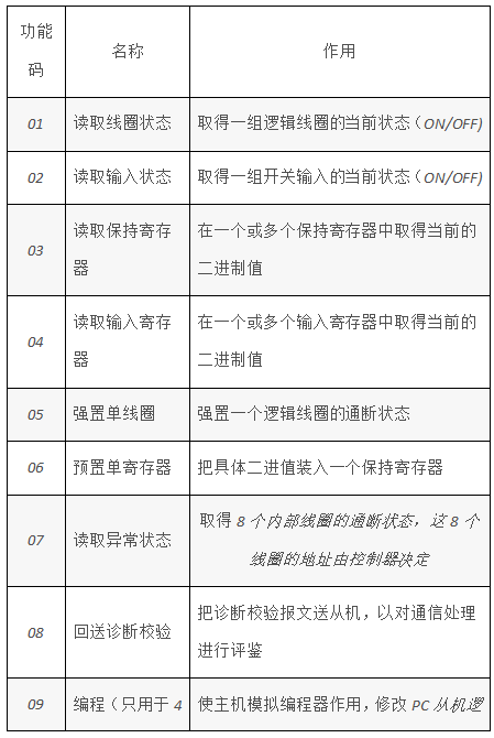
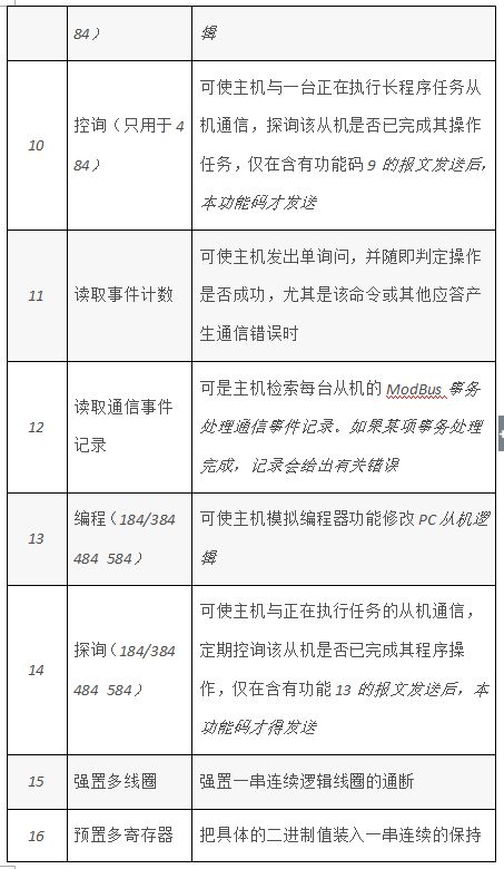
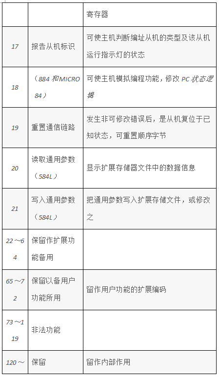
The Modbus protocol was originally developed by Modicon. The company became part of Schneider Automation (Schneider Automation) at the end of 1979. Now Modbus is the most popular protocol in the industrial field. This protocol supports traditional RS-232, RS-422, RS-485 and Ethernet equipment. Many industrial equipment, including PLC, DCS, smart meters, etc., are using Modbus protocol as the communication standard between them. With it, control equipment produced by different manufacturers can be connected to an industrial network for centralized monitoring. When communicating on the network, the Modbus protocol determines that each controller needs to know their device address, recognize the message sent by the address, and decide what action to take. If a response is needed, the controller will generate a response and send it to the inquirer using the Modbus protocol. The Modbus protocol includes ASCII, RTU, TCP, etc., and does not specify the physical layer. This protocol defines the message structure that the controller can recognize and use, regardless of the network through which they communicate. The standard Modicon controller uses RS232C to implement serial Modbus. Modbus's ASCII and RTU protocols stipulate the structure of messages, data, commands, and answering methods. The data communication adopts the Maser/Slave method. The Master sends a data request message, and the Slave can send data to the Master after receiving the correct message. In response to the request; the Master can also directly send messages to modify the data on the Slave to achieve two-way reading and writing. The Modbus protocol needs to check the data. In addition to the parity check in the serial protocol, the ASCII mode uses the LRC check, and the RTU mode uses the 16-bit CRC check. However, the TCP mode does not require additional check, because the TCP protocol is a Reliable connection-oriented protocol. In addition, Modbus adopts the master-slave mode to send and receive data regularly. In actual use, if a slave site is disconnected (such as failure or shutdown), the Master can diagnose it, and when the fault is repaired, the network can be automatically connected. Therefore, the reliability of the Modbus protocol is better. Let me briefly introduce to you. For Modbus's ASCII, RTU and TCP protocols, the TCP and RTU protocols are very similar. We only need to remove the two-byte check code of the RTU protocol, and then use the RTU protocol. Add 5 0s and 6s to the beginning of and send them out via TCP/IP network protocol. So here I only introduce Modbus ASCII and RTU protocol. The following table is a comparison between ASCII protocol and RTU protocol: Through comparison, it can be seen that the ASCII protocol and the RTU protocol have start and end tags, so it is more convenient to process the program, and because the transmission is all visible ASCII characters, it is more intuitive when debugging. Its LRC verification is also relatively easy. But because it transmits all visible ASCII characters, each byte of ASCII data transmitted by RTU needs to be transmitted with two bytes. For example, when RTU transmits a hexadecimal number 0xF9, ASCII needs to transmit'F'' The 9'ASCII code 0x39 and 0x46 are two bytes, so its transmission efficiency is relatively low. So in general, if the amount of data to be transmitted is small, you can consider using the ASCII protocol. If the amount of data to be transmitted is relatively large, it is best to use the RTU protocol. The following describes the verification of the two protocols. 1. LRC check The LRC field is a byte containing an 8-bit binary value. The LRC value is calculated by the transmitting device and placed in the message frame. The receiving device calculates the LRC during the process of receiving the message and compares it with the value in the LRC field in the received message. If the two values ​​are not equal, it means there is an error. The LRC checksum is relatively simple. It is used in the ASCII protocol to detect the contents of the message field except the beginning colon and the ending carriage return number. It just adds 1 to each data that needs to be transmitted after being superimposed by byte. Here is its VC code: BYTE GetCheckCode(const char * pSendBuf, int nEnd)//Get check code {BYTE byLrc = 0;char pBuf[4];int nData = 0;for(i=1; i;> 2. CRC check The CRC field is two bytes and contains a 16-bit binary value. It is calculated by the transmission equipment and added to the message. The receiving device recalculates the CRC of the received message and compares it with the value in the received CRC field. If the two values ​​are different, there is an error. CRC is to first load a 16-bit register with a value of all "1"s, and then call a process to process the values ​​in the current registers of the continuous 8-bit bytes in the message. Only the 8Bit data in each character is valid for CRC, and the start bit, stop bit and parity bit are invalid. During the CRC generation process, each 8-bit character is individually ORed with the contents of the register, and the result is moved to the least significant bit, and the most significant bit is filled with 0. The LSB is extracted for detection. If the LSB is 1, the register is equal to the preset value alone. If the LSB is 0, it is not performed. The whole process should be repeated 8 times. After the last bit (the 8th bit) is completed, the next 8-bit byte is ORed with the current value of the register separately. The value in the final register is the CRC value after all bytes in the message are executed. When CRC is added to the message, the low byte is added first, and then the high byte. Here is its VC code: WORD GetCheckCode(const char * pSendBuf, int nEnd)//Get check code(WORD wCrc = WORD(0xFFFF); for(int i=0; i>= 1; wCrc ^= 0xA001;} else{ wCrc >>= 1;}}} return wCrc;};> A command of the RTU protocol can be converted into a command of the ASCII protocol simply through the following steps: 1. Remove the CRC check of the command, and calculate the LRC check to replace it. 2. Convert each byte of the generated command string into the corresponding two-byte ASCII code, such as 0x03 into 0x30, 0x33 (ASCII code of 0 and ASCII code of 3). 3. Add the start mark ":" at the beginning of the command, and its ASCII code is 0x3A. 4. Add the end mark CR, LF (0xD, 0xA) at the end of the command, where CR, LF represent the ASCII code of carriage return and line feed. Therefore, we only introduce the RTU protocol below, and the corresponding ASCII protocol can be generated using the above steps. The following table is the function codes supported by Modbus: Among these function codes, the number 1, 2, 3, 4, 5, and 6 function codes are used for a long time, and they can be used to realize the read and write operations of the digital and analog quantities of the lower computer. 1. Read and write digital registers (coil status): Computer send command: [device address] [command number 01] [start register address high 8 bits] [low 8 bits] [read register number high 8 bits] [low 8 bits] [CRC check low 8 bits ] [Higher 8 bits of CRC check] Example: [11][01][00][13][00][25][CRC low][CRC high] The meaning is as follows: Device address: Multiple devices can be connected to a 485 bus. The device address here indicates which device you want to communicate with. In the example, I want to communicate with number 17 (17 in decimal is 11 in hexadecimal). Command number 01: The command number for reading digital quantities is fixed to 01. The upper 8 bits and the lower 8 bits of the starting address: indicate the starting address of the switching value to be read (the starting address is 0). For example, the starting address in the example is 19. The upper 8 bits and the lower 8 bits of the register number: indicate how many switching values ​​are read from the starting address. In the example, there are 37 switches. CRC check: check from the beginning to the beginning. I will introduce it at the end of this agreement. It should be noted here that the order of the high and low bytes of the CRC check in the command is opposite to the others. Device response: [device address] [command number 01] [number of bytes returned] [data 1] [data 2]...[data n] [low 8 bits of CRC check] [high of CRC check 8 bits] Example: [11][01][05][CD][6B][B2][0E][1B][CRC low][CRC high] The meaning is as follows: The device address and command number are the same as above. Number of bytes returned: indicates the number of bytes of data, that is, the value of n in data 1, 2...n. Data 1...n: Since each piece of data is an 8-bit number, each piece of data represents the value of 8 switches. Each bit of 0 indicates that the corresponding switch is off, and 1 indicates that it is closed. For example, in the example, it means that switch number 20 (index number is 19) is closed, number 21 is open, 22 is closed, 23 is closed, 24 is open, 25 is open, 26 is closed, and 27 is closed... If the switch value inquired is not 8 Is an integral multiple of, then the high part of the last byte is meaningless and is set to 0. The CRC check is the same as above. 2. Read only readable digital register (input status): It is similar to reading coil status, except that the command number of the second byte is no longer 1 but 2. 3. Write digital quantity (coil status): The computer sends commands: [device address] [command number 05] [high 8 bits of the register address to be set down] [low 8 bits] [high 8 bits of the data set down] [low 8 bits] [low 8 bits of CRC check Bit] [Higher 8 bits of CRC check] Example: [11][05][00][AC][FF][00][CRC low][CRC high] The meaning is as follows: The device address is the same as above. Command number: The command number for writing digital quantity is fixed to 05. The upper 8 bits and the lower 8 bits of the register address to be lowered: indicate the address of the switch to be lowered. The lower 8 bits of data and the lower 8 bits: indicate the state of the switch quantity that needs to be lowered. In the example, the switch is closed. Note that here can only be [FF][00] for closed [00][00] for open, other values ​​are illegal. Note that this command can only set the state of one switch. Device response: If successful, the command sent by the computer will be returned as it is, otherwise it will not respond. 4. Read and write analog registers (holding registers): Computer send command: [device address] [command number 03] [start register address high 8 bits] [low 8 bits] [read register number high 8 bits] [low 8 bits] [CRC check low 8 bits ] [Higher 8 bits of CRC check] Example: [11][03][00][6B][00][03][CRC low][CRC high] The meaning is as follows: The device address is the same as above. Command number: The command number for reading analog is fixed to 03. The upper 8 bits and the lower 8 bits of the starting address: indicate the starting address of the analog quantity to be read (the starting address is 0). For example, the starting address in the example is 107. The high 8 bits and the low 8 bits of the number of registers: indicate how many analog quantities are read from the starting address. In the example, there are 3 analog quantities. Note that an analog quantity needs to return two bytes in the returned information. Device response: [device address] [command number 03] [number of bytes returned] [data1][data2]...[datan][CRC check low 8 bits] [CRC check high 8 bits] Example: [11][03][06][02][2B][00][00][00][64][CRC low][CRC high] The meaning is as follows: The device address and command number are the same as above. Number of bytes returned: indicates the number of bytes of data, that is, the value of n in data 1, 2...n. In the example, the data of 3 analogs are returned. Because an analog requires 2 bytes, there are 6 bytes in total. Data 1...n: [Data 1] [Data 2] are the high 8 bits and low 8 bits of the first analog quantity, [Data 3] [Data 4] are the high 8 bits of the second analog quantity And the lower 8 bits, and so on. The values ​​returned in the example are 555, 0, 100. The CRC check is the same as above. 5. Read only readable analog register (input register): Similar to reading the save register, except that the command number of the second byte is no longer 2 but 4. 6. Write a single analog register (holding register): The computer sends commands: [device address] [command number 06] [high 8 bits of the register address to be set down] [low 8 bits] [high 8 bits of the data set down] [low 8 bits] [low 8 bits of CRC check Bit] [Higher 8 bits of CRC check] Example: [11][06][00][01][00][03][CRC low][CRC high] The meaning is as follows: The device address is the same as above. Command number: The command number for writing analog is fixed at 06. The upper 8 bits and the lower 8 bits of the register address to be lowered: indicate the address of the analog register to be lowered. The high 8 bits of the lower data and the lower 8 bits: indicate the analog data that needs to be lowered. For example, the value of register 1 is set to 3 in the example. Note that this command can only set the status of one analog quantity. Device response: If successful, the command sent by the computer will be returned as it is, otherwise it will not respond. We've been around for over 16+ years. We make sure our sound is The Best Sound. Customized Headphones, personalized gifts, promotional products custom , Bluetooth Earphones,Best Headphones TOPNOTCH INTERNATIONAL GROUP LIMITED , https://www.itopnoobluetoothes.com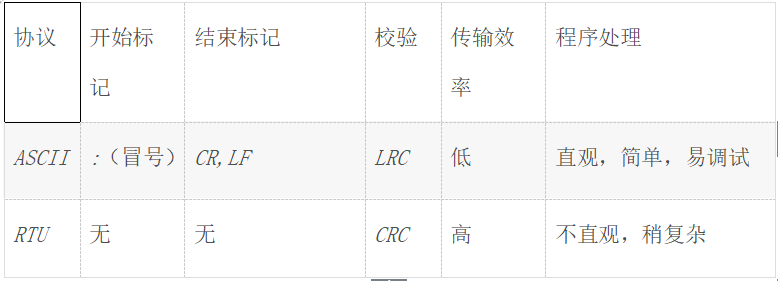
Our products include gaming headset, Bluetooth Earphone, Headphones Noise Cancelling, Best Wireless Earbuds, Bluetooth Mask, Headphones For Sleeping, Headphones in Headband, Bluetooth Beanie Hat, bluetooth for motorcycle helmet, etc
Manufacturing high-quality products for customers according to international standards, such as CE ROHS FCC REACH UL SGS BQB etc.
We help 200+ customers create custom Bluetooth headphones, earbuds, earphones, etc audio products design for various industries.