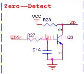
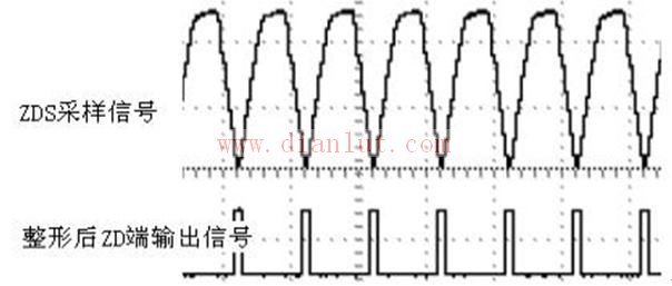
The zero-crossing detection circuit is shown in Figure 1. It is used to detect the zero-crossing point of AC220V, sample the full-wave rectified signal in the rectifier bridge, and form a shaping circuit through the triode and the resistor-capacitor to form a pulse wave, which can trigger an external interrupt. Zero detection. The sampling point and the shaped signal are shown in Figure 2. Pressure Gauge Without Capillary ZHOUSHAN JIAERLING METER CO.,LTD , https://www.zsjrlmeter.com
Test - lowercase jpg Kaixin micro test Adjustable capacitor Murata genuine original Test probe P100-M3 TZC3Z030A110R00 MURATA Murata adjustable capacitor original spot