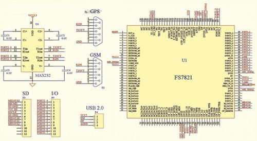
With the improvement of people's living standards, cars have gradually entered the ordinary family, and the car ownership in major cities in China has increased year by year. At the same time, the theft and robbing of cars has become a serious social problem. Although the application of various types of automobile anti-theft/alarmers in automobiles has solved the safety problem of automobiles to some extent, with the improvement of the means of thieves, most of the alarms are easily destroyed quickly. Most of the ways of car alarms are flashing lights and horns. The owner of the car may not be able to get an alarm, but the surrounding residents are seriously disturbed. In addition, the thieves destroyed the alarm, and after stealing the car, the appearance was slightly changed, and the car was like a sinking sea and could not be traced. In order to solve these problems, the design uses GPS monitoring to track the position of the car. In the case of theft, the GSM short message module can be used to send the GPS position of the car to the owner or the public security department at any time to speed up the detection of the case. This article refers to the address: http:// Figure 1 system function diagram System function This monitor is different from ordinary car alarms and does not provide functions such as sound and light alarm and car circuit cut-off when stolen. It is equivalent to a tracker with alarm function, using GPS positioning to determine whether the car has been stolen. After confirming that the car has been stolen, the location information of the car can be sent to the police at any time by using GSM SMS. This kind of monitor is a supplement to the general car alarm. It is not easy to be found, it can't be removed in a short time, and the positioning accuracy is high (about 10m). The system function of the entire monitor is shown in Figure 1. The monitor is installed in the concealed part of the car. It is usually powered by the car battery. After the car power is cut off, the battery can be automatically switched to the battery independently. The GPS receiving antenna is located outside the car, which is better for receiving signals. The basic way in which the entire monitor works is that the monitor is in a power-saving sleep state while the car is running normally. When the car stops and the owner leaves, the owner can use the mobile phone to send a text message to the monitor and command it to be in the monitoring state. At this time, the GPS receiving function of the monitor is turned on, and the information such as the position, speed and height transmitted by the GPS positioning satellite is periodically received, and the stationary position is marked as a safe position. When the thief destroys the general anti-theft system of the car, when the car leaves, the position coordinates received by the GPS change, when the speed and position deviation are greater than the set alarm value. The monitor will automatically send an alarm message to the owner's mobile phone, alerting the car to be moved and possibly stolen. After the owner alarms, in order to cooperate with the police to find the stolen car, the owner can send a command to the monitor again, open the timed message sending function, and send the current car coordinates to the owner or alarm center regularly. The electronic map can be very convenient. Find the current car location and quickly solve the case. The SD card that comes with the system can store information such as the coordinates of the car changes for a long time after the alarm, as evidence for solving the case and clues to find thieves. In order to realize the monitoring function, the system hardware design requires the monitor to have GPS receiving, GSM short message sending and large data storage functions, and has certain multi-tasking processing capability, low cost and small size. The hardware structure of the monitor is shown in Figure 2. Figure 2 monitor hardware structure diagram A suitable master chip will play an important role in the system. The FS7821LQ embedded chip is selected in this monitor. The FS7821LQ integrates the RISC-structured 8051 core, USB 2.0 controller, transceiver, NAND flash, SD and CF interface controllers. The embedded system composed of this chip is simple, powerful, and inexpensive, which is in line with the requirements of this design. The SMS function of the monitor mainly completes the reception of the owner's SMS command and the transmission of the GPS location data of the car. The system uses the mature GSM-RTU SMS module to complete. The module is embedded with GSM module, 16-bit low-power MSP430 MCU control management, core unit with telemetry remote control, 1 configurable standard serial port (RS-232C), standard antenna and SIM card interface. Insert the purchased SIM card into the SMS module, and complete the system (including the service phone number) settings, the serial port of the SMS module and the serial port 1 of the monitor (adding the level conversion chip to make it conform to the RS-232C level standard) Connected, the hardware installation of the SMS module is completed. The GPS module mainly completes the reception of GPS data of the car. The system selects the MG-30U/R-GPS module and adopts the second generation high-performance chip of SiRF (with 12 channels, which can receive 12 GPS satellite signals at most) for comparative solution. It can choose relevant data such as speed, position and altitude, and the price is low and the precision is high. The module output can be RS-232C interface, and the serial port 2 of the system main control chip FS7821LQ is connected with the GPS module. Because the amount of data transferred is not large, using the serial port to transfer data can avoid the trouble of using the USB interface to establish the main USB port on the system. Figure 3 shows the circuit design of the system hardware. The FS7821LQ has a complete SD card driver and interface. The system can directly connect to it with a 128Mb SD card. The general-purpose I/O port PORT2_0~PORT2_3 of the FS7821LQ chip is used to form two serial ports. After adding the MAX232 level conversion chip, the GPS and GSM modules are respectively connected. The FS7821LQ chip includes a function and hardware driver from the USB interface, and the interface reserved for USB 2.0 in the system is used as a product upgrade. In addition, the system also reserved 10 general-purpose I/O ports of the FS7821LQ as control ports for subsequent alarm functions. Figure 3 system hardware circuit design System software design Because this monitor includes a variety of more complex functions, it also has burst functions such as SMS sending and receiving and GPS receiving and other timing tasks, in order to better complete the task execution, in the embedded system, The μC/OS-II operating system was ported. As a free open source real-time embedded operating system, μC/OS-II provides multi-tasking switching capability and interrupt, UART driver and other functions, which can fully meet the requirements of this operating platform. As a basic task scheduling kernel, μC/OS-II only has the ability to switch tasks. The monitor can be divided into four tasks as shown in Table 1 according to its functions: the priority of the main task is the highest (10); The priority of sending and receiving tasks is second highest (12), which mainly includes receiving SMS function (including setting, switching monitor) and sending SMS function (sending GPS coordinates when 5s is alarmed). The time of this task is random and the real-time requirement is high. GPS receiving tasks receive GPS data every 5s, and analyze their coordinates to determine whether to alarm; data storage tasks store GPS coordinates every 60s after alarm (128Mb card can save about 1 month of data). Because the USB device and the SD card are used in the monitor, the USB and SD drivers must be mentioned in the software while having the hardware interface. Drivers for USB drivers and SD/MMC cards are provided in the development kit for the FS7821LQ chip, including support for standard MMC card commands; embedded 5B command memory; embedded 17B response memory; support for 1/4/8-bit data width; 20MHz clock frequency. In order to save the GPS data to the SD card in the form of a file, there must be a file system compatible with the PC. This monitor successfully transplants the simplified FAT16 file system and realizes free access of the file. Figure 4 Software state flow diagram development and prospects This embedded car monitor is designed with a number of proven technologies and modules. Its application is mainly to provide accurate car position information after warning and stolen when the car is stolen, can not replace the traditional car alarm, but can provide a very practical anti-theft function, providing fast and accurate search for stolen cars. information. With the development of technology, the integration of the controller and the main controller in GPS/GSM is bound to become the development direction, which will inevitably further reduce the cost and reduce the volume. At the same time, the monitor can be integrated with a general-purpose car alarm to develop a more complete system.
Bitcoin mining equipment is mainly highly specialized ASIC mill , The maximum computing power of a single miner is 110T/s( Ant S19Pro mill ), The scale of computing power of the whole network is 120EH/s above . Ethereum's mining equipment is mainly graphics card mining machine , Professional ASIC Mining machines are very few , On the one hand, it is because of the of Ethereum mining algorithm [ resist ASIC sex " Improved R & D efficiency ASIC The threshold of the miner , So how much do you know about the mainstream Ethereum mining machine ?
Ethereum mining algorithm has higher requirements for memory , The purpose of this design limits ASIC The use of chips in Ethereum mining . From the results , Most Ethereum mining machines are graphics card machines , This reflects the application of Ethereum mining algorithm ASIC Success on . From the absolute value of computational power scale , The computing power of Ethereum is about 200TH/s, The computing power of bitcoin is about 120EH/s, The latter is close to the former 60 ten thousandfold .
ASIC Mining machines have high computing power , Large power consumption , Like the latest ant S19Pro mill , Rated power consumption is 3250W, Need to consume... Every day 78 Degree electricity , According to the current currency price and 0.23 The electricity price in wet season is RMB , The proportion of electricity charge is 30.68%. Other older bitcoins ASIC mill , Like ants T17 series , The proportion of electricity charges generally exceeds 50%. by comparison , The power consumption of the graphics card miner is low , The proportion of electricity is also low . such as 5600XT8 Graphics card miner of card .
Ant S19-95T It adopts aluminum alloy profile electromechanical integrated design , Parallel four fan structure . According to the measured data , In line with and better than the official data .S19 The series is provided by TSMC 7nm chip , A new generation of customized chips with perfect whole machine architecture and high conversion rate APW12 Power Supply , Reduce power loss during conversion , Use more energy-saving , Greatly shorten the return cycle of the miner . In addition, the newly upgraded mining machine operation interface is also more humanized , Real time computing power . The average computing power and the operation of each chip are clear at a glance .
Shenma mining machine M30S-86T/88T/90T, Bit micro 2020 Launched in 2013 M30S Series of new mining machines , Announced that it would M30S The series is expanded to three 3X product . stay 3X In the new standard , Bit micro promises a one-year warranty for its series of products . This series of mining machines are provided by Samsung 8nm chip , Among them, god horse M30S series , The power consumption is 38J/T, Provide higher computing power , Lower power consumption and high stability.
Ethereum Mining Machine:Jasminer X4,Bitmain Antminer E9 (2.4Gh),iPollo V1,Jasminer X4-1U,iPollo V1 Classic, Ethereum Mining Machine,ETHW Miner,innosilicon a10 pro,E9 Antminer,Innosilicon A11 Shenzhen YLHM Technology Co., Ltd. , https://www.apgelectrical.com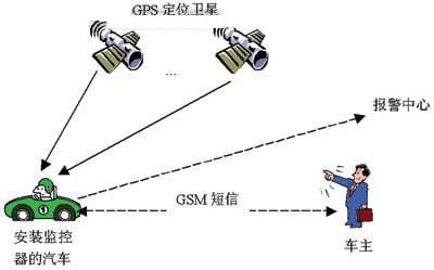
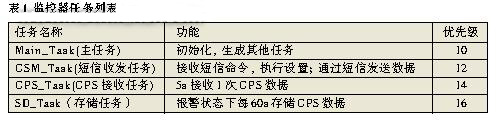
After porting the ç¤/OS-II and embedding the drivers for the USB and SD/MMC cards, the functions of the software installation system of the application level of the monitor are divided into multiple tasks with different priorities. The main task is used to generate other tasks with the highest priority (10); the GPS receiving task is responsible for controlling the MG-30U/R-GPS module, and obtaining the required GPS data from it, with the highest priority (12); The receiving and receiving task completes the function of receiving the owner's short message and transmitting the GPS data, and its priority is again (14); finally, the data storage function completes the GPS storage and system setting function of the SD card with a priority of 16. The message queue is also established in the program to complete the communication and data exchange between tasks. The software state flow diagram is shown in Figure 4. 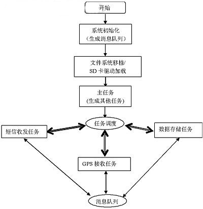
Jasminer X4-C 1U,iPollo V1 Mini SE Plus