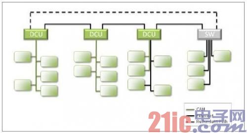
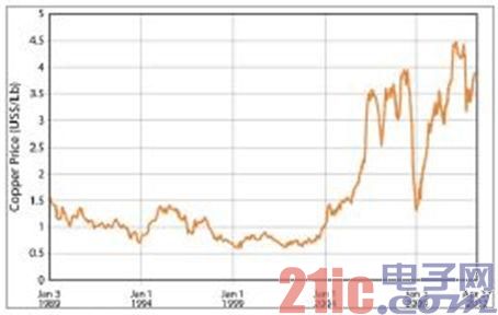
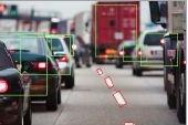
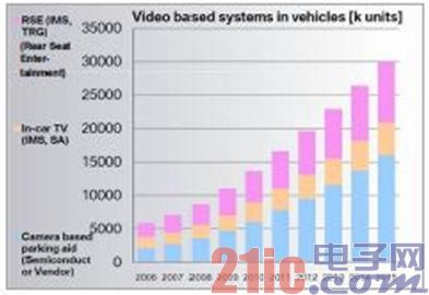
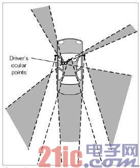
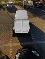
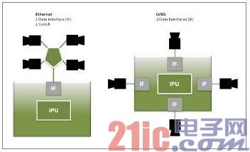
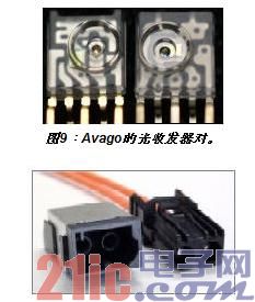
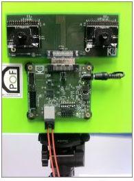
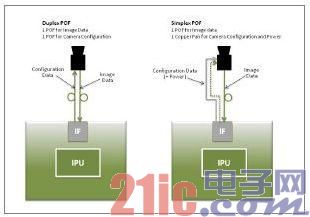
1 Introduction This article refers to the address: http:// The rapid growth of in-vehicle infotainment equipment and the rise of Advanced Driver Assistance Systems (ADAS) have created a need for more efficient interconnections between automotive interiors. By taking advantage of other technologies, Ethernet is the automotive network. The ideal choice. Plastic optical fiber (POF), a well-known transmission medium in the automotive industry, can now provide gigabit transmission capacity, making it the perfect solution for future automotive Ethernet networks and point-to-point link applications such as camera lenses. . 2 car Ethernet network Cars have quickly become an extension of the family, and infotainment systems are increasingly becoming the basic equipment for connecting neighboring devices and other vehicles in new cars. Internet and car infrastructure are becoming the future industry standard for car equipment. Similarly, driving assistance is also the main way to provide a safe corner of the car without a dead end, avoiding traffic accidents, because the car and infrastructure can be designed to achieve this goal without being mistaken or deliberately affected by driving, ADAS will join other passive And the active system becomes the standard car equipment. These feature-rich infotainment and driver assistance systems will dramatically increase communication bandwidth requirements and increase the complexity of automotive networks, as more complex automotive networks can affect reliability and maintainability, infotainment systems and driver assistance systems. The increase creates demand for new network solutions that go beyond point-to-point links or ring topology that currently do not provide inter-car communication. 2.1 Ethernet provides scalability and flexibility The Controller Area Network (CAN) is a communication protocol for the electronic architecture of the past 30 years. It is no longer able to meet the needs of future automotive architectures. On the other hand, Ethernet can provide a new generation of in-vehicle networks. The scalability and flexibility that the architecture requires. For most automotive OEMs, scalability is a key feature that can be used on multiple automotive production lines by means of a platform that is supported by network technologies that allow each car to be customized separately. High flexibility is also a key feature that allows automotive OEMs to offer multiple vehicle customizations without the need to change the network. The network configuration will automatically adapt to the specific equipment in the car, and the car manufacturer does not need to specialize in each model. Perform network configuration. 2.2 Ethernet application of upper and lower communication layer Ethernet can be used as the lower communication layer of the standardized IP diagnostic interface. It is developed by ISO 13400 Diagnostic Communication over Internet Protocol (DoIP) and is expected to be adopted by most automotive OEMs worldwide. This interface based on the same IP protocol as the Internet simplifies the diagnosis of in-vehicle systems. As a lower layer technology, Ethernet can be smoothly interfaced with IP, which is one of the reasons why it is currently widely used in Internet connection networks. Ethernet also brings seamless connection with other upper layer protocols. For example, it can assist video and audio synchronization or secure transmission of timely information, and audio and video synchronization (AVB protocol stack, IEEE 802.1 Qav, which is very important for infotainment networks). 802.1 AS, 1722) ensures the synchronization of video and audio between different screens and speakers in the car. Similarly, timely information provided by the Precision Time Protocol Stack (IEEE 1588v2 and 1722) is very important, especially for ADAS, which ensures that information can reach its destination without delay to meet the requirements of security applications. 2.3 layered architecture of the Ethernet backbone All major automakers agree to the benefits of splitting the car into different functional blocks. In this new structure, the car will work together and share information in several different areas, such as powertrain, body control, transmission. And security systems, etc. In each field, the form of connection used will be based on the functions to be performed and the needs of each domain. Typical cross-domain networks will be based on FlexRay, MOST, Ethernet (first generation based on BroadR-Reach), CAN or LIN, etc. . In order to meet the new demands brought by the layered architecture, a broadband network will be required for reliable communication between all areas. Currently Ethernet seems to be the best choice. However, the best physical layer of gigabit speed is still under discussion. Among them, the POF-based optical physical layer can provide 1Gbps bandwidth requirements to meet the requirements of current and next-generation systems, while at the same time bringing the advantages of lower cost and lighter weight. Figure 1 shows the centralized architecture currently in use. In this architecture, a single central gateway (CGW, Central GateWay) provides CAN cabling, LIN cabling, FlexRay cabling, and MOST cabling. In a distributed backbone architecture, the automotive subsystem is differentiated into a single network technology, such as a CAN or Ethernet zone group, or a mix of technologies. Figure 1: Centralized architecture. Figure 2: Daisy chain backbone with optional redundant paths. Through the new domain-based architecture, it creates the backbone requirements for connecting all domain control units (DCUs) and exchanges between each domain. Although there are several backbone structures to choose from, it seems that the most competitive is to provide Select the daisy chain backbone of the redundant path. Since all areas are connected through a single backbone, its size must be automatically adapted to the amount of data movement between the domains. For future projections, ADAS and infotainment systems plus each area of ​​the car will require 1 Gbps. backbone. 3 unique challenges in automotive applications The physical layer of the network technology used by the automotive network must meet the unique challenges of the automotive environment and cannot significantly increase the cost. The final cost of the system is determined not only by the performance itself, but also by the environmental conditions of the vehicle, which in most cases is Will increase the final cost. The challenges facing automotive networks include: â—Vibration The network technology used must be able to withstand the vibrations that the car has in a continuous travel environment. Vibrations can affect all of the mechanical components and are particularly susceptible to damage to the electrical connectors, thus placing stringent restrictions on cables and connectors. â—temperature The temperature range in different areas of the car will vary depending on the location of the network, and the maximum temperature in most automotive areas is approximately 105 °C. â—weight The use of weight as a network vehicle is important because it directly affects fuel consumption and costs, as well as associated carbon emissions. â— Cost predictability The copper-based physical layer is affected by the unpredictability of copper prices. Copper prices have risen sharply in the past 10 years, and the inability to estimate costs steadily has become a negative factor affecting copper-based cable solutions. â—Electromagnetic compatibility (EMC, ElectroMagnetic Compatibility) Electromagnetic radiation and interference are a major challenge for automotive networks, and electrical-based communications, such as the use of copper as a physical layer, are particularly susceptible to electromagnetic interference (EMI, ElectroMagnetic Interference). â— length The typical length of a car network is about 5 meters, and some networks may extend to 15 meters. Any communication technology used in a car network must be able to provide sufficient signal-to-noise ratio (SNR) while covering these length ranges. degree. 3.1 POF backbone of the car network POF is the ideal backbone for automotive networks. As an optical medium, POF does not have typical limitations based on electrical physical layers such as EMI, weight and cost predictability. Compared to other hard-clad fibers, due to the MOST and FlexRay protocols. The POF, which is famous for its automotive market, is easier to handle and has lower installation and maintenance costs. Finally, due to KDPOF technology, developed by VDE and ETSI, POF can overcome existing opto-electronic limitations and achieve 1Gbps performance required by strict automotive standards. To meet the unique challenges of the automotive environment, POF offers several advantages over copper solutions and even hard-clad fibers. â—Vibration Since POF is an optical technology, electrical contacts are not used, so electrical noise due to vibration can be avoided, and the larger core diameter (1 mm) of the POF also makes it sufficiently stable that it is immune to vibration. â—temperature POF is a polymer material that is more susceptible to temperature than copper or hard-clad fibers. However, POF solutions for the most common automotive environments have high-temperature POFs that can be used in all target automotive applications. Although the current temperature limit of optical transceivers is 95 ° C, the latest Avago Gigabit POF transceivers have set a target of 105 ° C. â—weight POF is much lighter than copper cables. It is only one-sixth of UTP Class 5 copper cable. The lighter weight of POF extends to all communication connections in the car, which can bring a significant weight advantage over copper cables. â—Predictability of price Polymer is a material that is not affected by market price fluctuations. On the contrary, copper has a large price fluctuation, which has fluctuated more than four times in the past 10 years. As shown in Figure 3, the price of copper in 2002 was USD$1.00 per pound. In 2012 it was close to USD$4.00 per pound. Figure 3: Trend chart of copper price changes from 1989 to 2012. (Source: InfoMine) â—Electromagnetic compatibility (EMC) System design engineers prefer optical solutions such as POF that are not affected by electrical noise, which translates into better noise margins and simpler system solutions. System testing can be achieved with lower development costs and shorter time to market. Time course is simplified. â— length Gigabit POF technology can extend the typical car's 15m target length to 40m, plus all the connectors on the line, so it can provide new applications for buses and trucks, while meeting the strict noise margin of shorter vehicle targets. degree. 3.2 POF for low speed links Although POF technology can reach 1Gbps bandwidth, it can also be applied to existing 100Mbps systems. This means that POF can not only meet the needs of Gigabit backbones for future automotive network applications, but also for lower speeds in existing vehicles. Communication bus application. Two key examples of POF for lower speed applications include hybrid or electric trains as well as buses and trucks, which have very high immunity requirements for EMC, and hybrid or electric trains are resistant to electrical noise solutions such as POF. Ideally, weight is an important key due to the use of a relatively large battery in these environments, and the lighter weight of the POF offers significant advantages over other technologies. For larger buses and trucks, POF-based lower speed solutions can extend the network to over 40 meters or even over 100 meters, providing new applications for buses and trucks. 4 Ethernet camera lens application The current trend in the automotive market is to load more camera lenses in the car, because safety-related imaging applications have gradually become the standard of today's cars. According to the TSR estimates of the consulting company, the proportion of vehicles integrating CMOS sensor car camera lenses has been increased by 2008. The 20% of the year has increased significantly to over 70% in 2013. The development of in-vehicle electronic vision systems is a growing area for the automotive market, especially for driving and other road users, including the improvement of safety requirements for vulnerable road users such as pedestrians. The car camera system is designed to display the area around the car. It usually covers the blind spots of the car. Major automotive markets such as Europe, Japan and North America have now begun to enter legislation to help avoid harm to vulnerable road users, with special emphasis on the use of vision systems. This trend is also rapidly driving the adoption of ADAS systems, please refer to Figure 4, previously Used only in high-end vehicles, these new safety systems are quickly added to lower-end cars after a significant reduction in production costs. Figure 4: Object detection for the ADAS system. Industry estimates that in 2017, vehicles can not only reach the target five-star New Car Assessment Program (NAC) without ADAS. Therefore, leading automakers must add at least one ADAS system as standard equipment at that time. The large growth of the ADAS system, as shown in Figure 5, will create a market demand that can connect all camera lenses, electronic control units (ECU) and human machine interface (HMI). Figure 5: Estimation of the increase in the car video system. (Source: IMS, Strategy Analytics (SA), Gartner, ABI Research div, semiconductor manufacturer) As an example, a car usually has at least 5 blind zones requiring several visual camera lenses to provide regional security scanning, as shown in Figure 6. The five blind zones including the left driver's seat can be seen in the figure. The size of the blind zone is determined by the vehicle design and The perspective of the mirror is determined. Figure 6: 5 typical blind spots for most cars. (Source: IVSCS 2008 July 22 - 24, 2008, Dublin, Ireland) Some automakers have launched or plan to introduce a 360-degree imaging system that uses at least four camera lenses to provide integrated images around the vehicle, as shown in Figure 7. Figure 7: Example of a 360-degree imaging system. 5 interconnection alternatives There is no single standard interface for automotive camera lenses. The dedicated serial link is the most common camera lens interface. The interface between the camera lens and the Image Processing Unit (IPU) or the display determines the way in which different camera lenses are interconnected in the same system. For example, LVDS is an interface that allows only the lens and IPU or display to be connected point-to-point. If the system consists of multiple camera lenses and an image processing unit, then only the top of each lens can be directly connected to the central unit. When the car has multiple ADAS and each ADS is connected by several interconnected camera lenses When it is composed, the way that it is directly connected can result in unacceptable wiring lengths and the number of connectors and interfaces. If you use Ethernet as the camera lens interface instead of the LVDS dedicated link, you can simplify the network. Although you use a point-to-point interface like LVDS, Ethernet uses packet switching, which can be done without reconfiguring system software and hardware. Any expansion or reduction, the network topology is more simplified, Figure 8 is a comparison of the simplified layout of Ethernet and LVDS. Figure 8: Comparison of Ethernet and LVDS when connecting four camera lenses to an Image Processing Unit (IPU). Dedicated direct connection can bring the benefit of predictable data arrival time, because there is no packet exchange on the connection, so there will be no unexpected delay. Ethernet can be used in the upper layer, such as audio and video bridge (AVB, Audio Video Bridging). Protocols such as the same predictability, but this requires more complicated calculations. In general, there is a trade-off between direct connection, simple connection, and Ethernet-based connectivity. For a simple single camera lens system, direct connection is the best choice, but when using a complex ADAS system, Ethernet Interface and topology are the most suitable technologies. 5.1 POF as the physical layer The physical layer connecting the camera lens and image processing unit or display screen in the ADAS system can use KDPOF's 1Gbps POF technology with Avago's optical transceiver, as shown in Figure 9, by Yazaki in a small-sized connector system, as shown in Figure 10. . Figure 10: Yazaki's small-sized connector system. KDPOF Application Specific Standard Product (ASSP) can be directly connected to a dedicated data link such as DVP or through a native Ethernet connection port such as RGMII or SGMII, which means that whether it is LVDS type or Ethernet-based ADAS system It can be done simply with the KDPOF product architecture. 5.2 Advantages of POF compared to copper cable systems Figure 11 shows a practical example of KDPOF Gigabit POF technology in an ADAS application. The prototype shown in the figure consists of two camera lenses connected to the IPU via POF in stereo mode. The display shows shape recognition and depth calculation. The image is used as a function input for driving support such as collision warning, pedestrian detection or intelligent fixed speed control. The camera lens samples 30fps frame at 1280 x 800 pixels, and the binary stream obtained is 960Mbps. Figure 11: Two camera lenses connected in a stereo configuration, the interface sends 1Gbps data to the IPU via POF. The initial configuration of the camera lens can be completed in two ways. The first option is based on duplex POF, one fiber is used as the uplink, the other is used as the downlink, and the second option is to use the simplex POF to transmit the image data. To the IPU, a parallel simplified and low-cost LIN-type copper cable pair is used as a channel for sending and starting configuration to the camera lens. This parallel channel can also be used to remotely provide camera lens power, saving additional cable pairs. Figure 12 depicts this. Two choices. Figure 12: Different practices for Ethernet POF camera lens control. in conclusion With the growing demand for infotainment networks and ADAS systems, the trend to move to new backbones is becoming more apparent, the advantages of Ethernet, coupled with the use of KDPOF 1Gbps plastic fiber optic ASSP, Avago optical transceivers and Yazaki Inc. The combination of size optical connectors provides a highly scalable and flexible solution that meets the ever-changing needs of automotive networks. 3.2V105Ah Lithium Ion Battery,105Ah 3.2V Phosphate Battery Cell,3.2V105Ah Deep Cycle Solar Battery,3.2V 105Ah Lifepo4 Forklift Battery Jiangsu Zhitai New Energy Technology Co.,Ltd , https://www.zhitaibattery.com