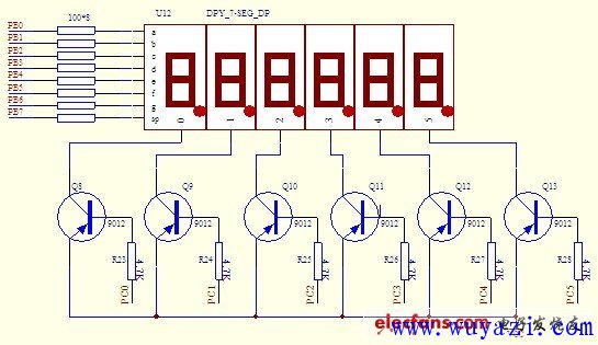
Dynamic Scan Display: The following figure shows the dynamic scan circuit diagram of 6 common anode LEDs. In the figure, port B of 8155 is connected to all dp(sp), g, f, e, d, c, b, a leads, and each LED control terminal G (ie, 0, 1 inside each digital tube shown in the figure) , 2, 3, 4, 5) is connected to the C port of the 8155, so the B port is a letter port, and the C port is a word port, because the CPU can control whether each LED is lit through the C port. Type1 To Type2 EV Charging Cable Type1 To Type2 Ev Charging Cable,Type 1 To Type 2 Charging Cable,Type 1 And Type 2 Ev Charging,Type 1 To Type 2 Cable Yangzhou JERI New Energy Co., Ltd. , https://www.jrevcharging.com