Figure 2: RF immunity at the CAN bus is enhanced This article refers to the address: http:// The data line choke can significantly improve the reliability of the CAN bus system. This is why European car manufacturers require the use of data line chokes. Although higher inductance chokes will result in better electromagnetic compatibility due to higher attenuation, to choose the most suitable choke, stray inductance, signal integrity, ground drift, and lead must also be considered. Factors such as robustness. The EPCOS B82789 series has an inductance range of 11 to 100 μH. FlexRay electromagnetic compatibility and electromagnetic interference FlexRay is a serial bus system with defined delay and fault tolerance. FlexRay is defined by the FlexRay Consortium. The FlexRay Alliance was founded in 2000 by BMW, Motorola (now Freescale, Freescale) and Phillips (now NXP, NXP), Bosch, General Motors, Volkswagen, and other companies later joined. FlexRay is designed to meet the higher demands of future automotive networks, especially fast data rates, real-time responsiveness, and fault tolerance. However, the current focus is on faster data rates. The Physical Layer Application Guide clearly states the overall requirements for the FlexRay network data line chokes, such as lead resistance (<1 Ω), inductance (>50 μH), and stray inductance (<1 μH). The measurement of electromagnetic radiation and electromagnetic interference is the same as that of the CAN bus. However, due to the higher transfer rate of 10 Mbit/s, signal integrity needs to be checked more carefully. Figure 4 shows the corresponding evaluation results of DPI measurement of a choke coil with various inductances and a test panel without a choke coil. Figure 5 shows the results of electromagnetic interference measurements using another test board, also for chokes with different inductances. It is clear that the use of data line chokes improves electromagnetic compatibility and reduces interference emissions. When the inductance is higher, the effect is greater. However, higher inductance values ​​can have a negative impact on signal integrity. The application of chokes has significantly improved electromagnetic compatibility immunity. The optimum inductance value for the overall system can be chosen from different inductors. The application of the B82789C0104 choke achieves the best signal integrity consistent with the FlexRay physical layer specification. This choke was then selected as the reference model for the qualification test. Model library for product development EPCOS currently offers appropriate simulation models to increase the efficiency of designs with new chokes. To this end, the electrical characteristics of the choke over the entire relevant frequency range are defined and included in the corresponding model. Because the terminal capacitance and inductance and the connected resistance are both user-designed, they are not included in the model. The customer can evaluate the function of the choke without having to perform a time-consuming overall system design. EPCOS is now available for simple models for initial design evaluation, which enable fast and accurate simulations. Advanced models provide more accurate simulation results, but require longer simulation times. Bus choke overview table 11 60 300 250 B82789C113N* B82789C113H* twenty two 100 250 580 B82789C223N* B82789C223H* twenty two 3000 250 580 B82789S223N* B82789S223H* 51 100 250 550 B82789C513N* B82789C513H* 100 250 150 1500 B82789C104N* B82789C104H*
This series is a professional floor-mounted LED Screen for both indoor and outdoor use, with a very strong load-bearing capacity. Suitable for various entertainment places, like KTV, bars, shopping malls, amusement parks, sports fields and so on. This product has a laser sensor function, which allows people to interact with video games, which is very interesting. Dance Floor LED Screen is a very good choice for a special solultion of advertisiment on everywhere, or make your stage more interesting and pretty.
Dance Floor Led Screen,Stage Pantalla Led Screen,Rentall Eventos Led Wall,Stage Pantalla Led Display Guangzhou Cheng Wen Photoelectric Technology Co., Ltd. , https://www.nbcwdisplay.com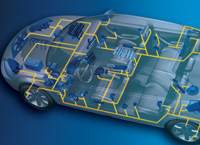
Bus choke
Data line chokes exist in almost all modern cars. Without the data line choke, electromagnetic compatibility and trouble-free operation of automotive electronics cannot be guaranteed. EPCOS now offers a wide range of models in different package sizes and versions to meet the specific requirements of the car. The B82789 series chokes are designed for powerful automotive bus systems such as CAN or FlexRay. When the above-mentioned choke is applied to the data line, the coupling interference can be suppressed and the data bus can be prevented from being disturbed. The series operates at 42 VAC or 80 V DC and has a rated inductance between 11 and 100 μH and a current rating between 150 and 300 mA.
Automotive bus systems must meet advanced electromagnetic compatibility requirements: immunity to transients, electrostatic discharge (ESD), and electromagnetic interference (EMI). However, the bus system cannot interfere with other electronic components, that is, interference radiation must be minimized. However, as the proportion of electronic devices inside the vehicle increases, it is impossible to pre-test electromagnetic compatibility under all conditions, and there is a risk of failure or even damage to the control device. The EPCOS data line chokes facilitate the resolution of the above problems. 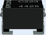
This test structure is used for electromagnetic interference measurement and measurement of bus choke effect 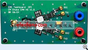
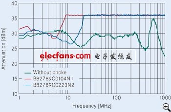
Attenuation (dBm) No choke frequency (MHz) The application of chokes greatly increases the immunity. 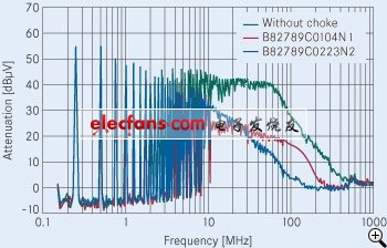
Figure 3: Noise attenuation at the CAN bus is reduced without choke attenuation (dBμV) Frequency (MHz)
The CAN bus choke greatly reduces RF emissions, thereby avoiding interference with other electronic systems. 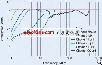
Figure 5: Interference radiation at the FLEXRAY bus is reduced without choke chokes 25 μH
Choke 2 μH choke 51 μH
Chokes 11 μH Chokes 100 μH 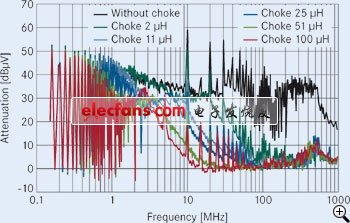
Attenuation (dBμV) Frequency (MHz)
The FlexRay bus choke also significantly reduces RF emissions in the FlexRay system.
The eye diagram is suitable for studying the signal integrity of FlexRay. If the curve of the data signal is outside the shadow range, data transmission can be guaranteed. These requirements can be achieved by using a B82789C0104 choke with an inductance of 100μH (see Figure 6). In view of the fact that the results of these electromagnetic compatibility measurements and the impact on the data signal are negligible (ie signal integrity can be guaranteed), the EPCOS B82789C0104 N002 (two-wire winding) choke is selected as the FlexRay physical layer qualification test. Reference model. 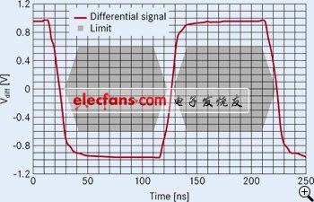
Inductance [μH] Stray inductance [nH] Rated current [mA] DC Resistance
[mΩ] Order code (125°C version) Order code (150°C version) 
Data line choke for automotive networks
In recent years, the proportion of electronic devices in automobiles has increased significantly. The development of this trend has added more features to improve the safety, efficiency, reliability and convenience of automobiles and reduce emissions. Corresponding to this is the increasing demand for bus systems: ensuring reliable communication between the most diverse control units. In particular, safety-critical applications controlled via bus systems such as Controller Area Network (CAN) or FlexRay systems must meet the highest electromagnetic compatibility specifications. The common mode choke (CMC) in the data line enhances protection against faults caused by electromagnetic compatibility issues.
The complexity of contemporary motor vehicle control functions lies in three points: faster data rates, deterministic latency performance, and fault tolerance. Cost-based functional or multimedia functions are connected by a LIN (Local Area Network) or MOST (Media Oriented System Transport) bus, while CAN or FlexRay bus systems are used for safety-critical functions such as engine control, ABS system and airbags, etc. CAN and FlexRay are twisted pair with deterministic delay for fast data rates (CAN bus: 1 Mbit∕s; FlexRay bus: 10 Mbit∕s). The physical layer and data transfer protocols of both bus systems have been optimized to ensure high reliability. However, in view of the increasing complexity of modern vehicles, the above-mentioned measures alone cannot completely prevent malfunctions caused by electromagnetic compatibility problems.
In general, differential mode and common mode interference must be distinguished. Differential mode interference coincides with the data signal, while common mode interference is grounded, which is due to imbalance and parasitic effects. To minimize common mode interference, special attention must be paid to the wiring of the bus signal lines, the termination filters, the connectors, and the board itself. The parasitic capacitance and inductance of the feedthrough or connector, as well as the layout of the bus signal leads on the board, can cause asymmetry and cause common mode interference.
Electromagnetic compatibility measurement (implemented on the test board)
A commonly used method for determining RF-affected electromagnetic compatibility is the Te Direct RF Power Injection (DPI) method: coupling a signal from a signal generator (up to 36 dBm) into a bus lead and observing the signal output. If a fault occurs, the signal level of the access signal is recorded. This process is repeated step by step for each corresponding frequency within the relevant range. The RF interference radiation of a particular bus structure is determined by the test receiver and is used to measure the common mode voltage at the bus and all inputs and outputs.
With and without the EPCOS choke, we use the DPI method to perform RF immunity and interference radiation measurements on the test board. The corresponding results of the CAN bus can be seen from Figure 2 and Figure 3. Obviously, the use of the B82789 common mode choke greatly improves RF immunity. At the same time, the use of chokes in the data line also greatly reduces the interference radiation.