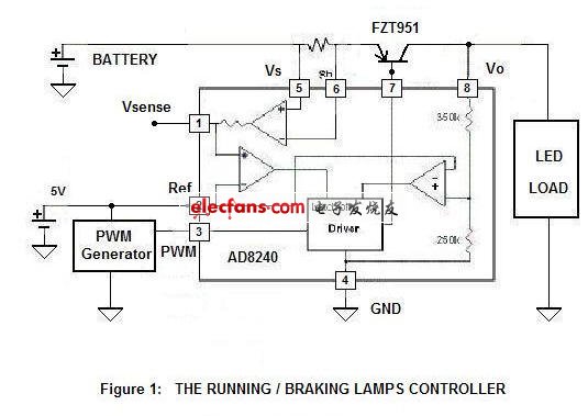
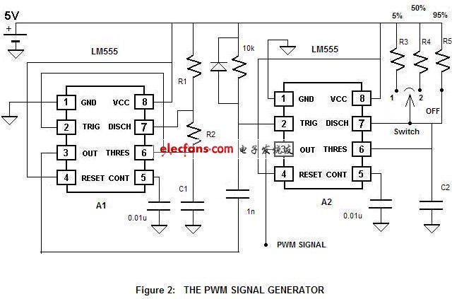
Red LEDs are now widely used in tail lights. Although cost is still an issue, safety, environmental protection and flexible styles and other factors tend to adopt LEDs. One of the most popular applications is the central brake light. This design concept shows the method of using the same LED array for the taillights and brake lights. Figure 1: Driving / brake light controller LED (Light Emitting Diode) brightness is generally expressed by Luminous Intensity, the unit is candela cd; 1000ucd (microcandela) = 1 mcd (millicandra), 1000mcd = 1 cd. The light intensity of a single LED for indoor use is generally 500ucd-50 mcd, while the light intensity of a single LED for outdoor use should generally be 100 mcd-1000 mcd, or even more than 1000 mcd. Figure 2 shows the PWM generator, which consists of two 555 timers. The PWM signal controls the LED brightness. When the PWM input is high, VO turns on; when the PWM input is low, VO turns off. Figure 2: PWM signal generator PWM signal generator 1. Input power supply voltage AC220V ± 10% 2. Two independent PWM signal outputs, frequency output fluctuation ≤0.01Hz at no-load, duty cycle output fluctuation ≤0.01%, stable output time ≤0.5s3. Frequency Continuously adjustable in the range of 0 ~ 9999Hz, accuracy 0.1%, 0 ~ 999.9Hz deviation ± 0.1Hz, 1000 ~ 9999Hz deviation ± 0.5Hz. 4. High and low levels are continuously adjustable, low level range 0 ~ 15V, high level range 1 ~ 30V; rising / falling edge time ≤18ns. 5. The duty ratio is continuously adjustable within the range of 0.1 ~ 99.9%, with an accuracy of 0.1% and a deviation of ± 0.01%. 6. Each output runs in 10 steps. You can set the specific parameters of each step to select the frequency and duty cycle you need. 7. The structure adopts horizontal cabinet, the material is aluminum alloy, spray beige paint, protection grade IP54. 8. Rated output current of signal generator: 200mA. 9. Configure standard RS232 communication (with upper computer software), operate it through the upper computer. 10. The single machine is operated by a small keyboard with 20 keys, which is easy to operate. AD8240 provides a low-power, low-cost, small package solution. The internal current-sense amplifier measures the voltage across the external shunt resistor; when the current measurement falls below the preset threshold, it indicates that an open LED has occurred. When the output of the sense amplifier exceeds 5 V, the internal comparator will cause the driver to lock the output voltage. In the next PWM cycle, the latch is reset. By measuring the output of the sense amplifier, the overcurrent condition can also be detected. Since the inductor required for the switch design is not needed, the cost can be further reduced; and the operating power consumption of the LED lamp is much lower than that of the incandescent lamp, so no switch driver is required. The switching of the LED depends on the digital voltage on the CMOS-compatible PWM pin (AD8240 pin 3). For simple switch control, this voltage can be continuous; for dimming control, this voltage is PWM. The PWM frequency should be below 500 Hz, and the duty cycle should range from 5% to 100%. Typical values ​​are 5% (when driving) and 95% (when braking). In Figure 2, the PWM frequency is determined by R1, R2, and C1 of timer A1. The pulse period is: T = 0.693 (R1 + 2 R2) C1 When R1 = 49.9 kΩ, R2 = 10 kΩ, and C1 = 0.1 μF, the period is 4.84 ms, or approximately 206 Hz. Timer A2 converts this signal to a pulse width modulated signal, the duty cycle of which is determined by R3, R4, R5, and C2. The pulse width is determined by the following formula: Pulse width = 1.1 RC2 Where R is equal to the parallel resistance of R5, R3 and R5 or the parallel resistance of R4 and R5, depending on the switch position. When R3 = 2.37 kΩ, R4 = 45.7 kΩ, R5 = 42.4 kΩ, C2 = 0.1 μF, the duty cycle is 5% (switch in position 1), 50% (switch in position 2) or 95% (switch in OFF position). This circuit provides a method of driving and monitoring LEDs with only two wires (power and ground) using a constant voltage. Many designs use a chassis or shared ground return, in which case two wires can be reduced to one wire. Currently, these lights are controlled and driven by the body control ECU (Electronic Control Unit). Please note that the LED brightness increases as the duty cycle increases. When the brake is depressed, the duty ratio is 95%, and the LED array is the brightest. During normal driving, the duty cycle is 5% and the LED array is dimmed. Two working states share a LED array can reduce costs. If a short circuit or overload condition occurs, the voltage on Vsense (Pin 1) drops to 0 V and the output is turned off. This circuit will reset in the next PWM cycle. If this continues, the AD8240 will try to drive the output to 12 V, shut down and restart after each PWM cycle. When this kind of constant voltage architecture is adopted, the control and driving functions of the LED remain in the ECU, and only a few design modifications need to be made. As the society progresses, the LED will be greatly accepted by people and enter people's daily life. British Standard Gang Switch And Socket British Standard Gang Switch And Socket,Standard Gang Switch And Socket,Standard Gang Switch,Standard Gang Switch For Sale ZHEJIANG HUAYAN ELECTRIC CO.,LTD , https://www.huayanelectric.com