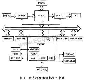
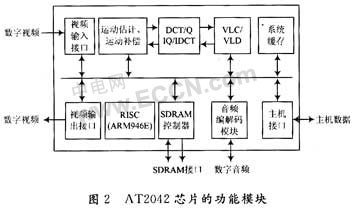
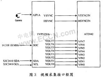
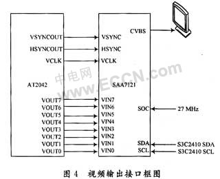
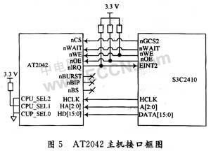
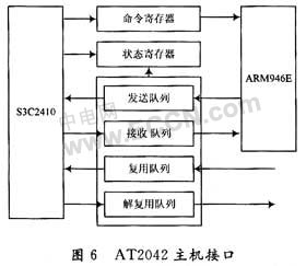
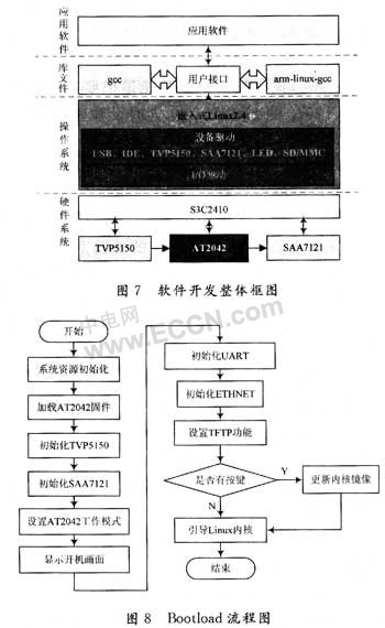
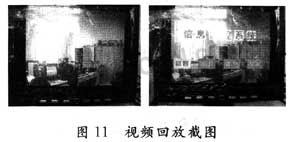
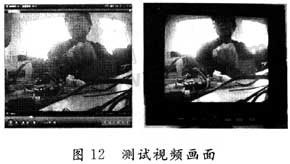
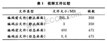
With the rapid development of video compression technology, new video compression standards are constantly being introduced. MPEG-4 is another ISO/IEC standard developed by the International Moving Picture Experts Group (MPEG) following MPEG-1 and MPEG-2, namely ISO/IEC 14496. It achieves higher audio/video compression and content-based interaction. At present, many companies at home and abroad are developing products related to the MPEG-4 video standard, and the most representative one is the Digital Video Recorder (DVR). This article refers to the address: http:// 1 hardware design of digital video recorder In the design and implementation of digital video recorder based on S3C2410 and AT2042, the terminal equipment is based on Samsung's 32-bit processor S3C2410 as the main control processor, and uses the AT2042 chip of Pentamicro to complete dual-channel video encoding and decoding. Features high resolution and high quality. This article will introduce the overall system design of this terminal, and analyze the system hardware and software design in detail, and finally give the test results and conclusions. According to the needs of the market, the system is expected to achieve the following indicators: (1) Implementing encoding and decoding of the MPEG-4 standard for video data; (2) The codec pixel is 720X576 pixels, achieving 25 f/s; (3) Implementing JPEG encoding and decoding; (4) Implement USB/SD card storage. 1.1 The overall design of digital video recorder based on S3C2410 and AT2042 The system mainly relies on the codec function of AT2042. The hardware block diagram of the system is shown in Figure 1. It is mainly composed of video coding subsystem, main control system, data processing subsystem and video decoding subsystem. The function module of AT2042 chip produced by South Korea's Pentamicro company is shown in Figure 2. The AT2042 is a 2-channel audio and video codec (A/VCODEC) chip with built-in microcontroller ARM946E, which mainly encodes and decodes video and voice data. Support a variety of audio and video codec standards, can directly interface with IBM, Motorola, ARM, XscaIe and Axis, without additional circuitry. 1.2 Video codec circuit design The video codec circuit mainly includes a video codec circuit and a video compression/decompression chip AT2042. Among them, AT2042 is mainly responsible for hardware compression and decompression of digital video data, and video codec circuit is an interface circuit between baseband analog video signal and AT2042, which includes a video encoding chip and a video decoding chip, mainly responsible for video. Analog/digital and digital/analog conversion of data, and conversion of digital video signal formats. In the compression coding process, the input NTSC/PAL/SECAM video signal is first processed by the video decoding chip to generate 8 b ITU-R BT.656 digital video signal conforming to the AT2042 video interface standard. Under the control of the external main CPU, the digital video data is hardware-compressed and encoded by the compression/decompression chip AT2042, and the generated encoded data stream is output through the integrated Mux FIFO interface of the chip. The decompression coding of the network video server is the inverse process of compression coding, and the data stream that needs to be decompressed is input through the Demux FIFO interface integrated in the AT2042. The video capture interface block diagram is shown in Figure 3: The camera captures the output signal as NTSC, PAL or SECAM TV signal, which must be decoded by video to be converted into a digital signal suitable for encoding by AT2042. TVP5150 is a TV signal decoding special chip produced by TI Company. It performs A/D conversion on the input analog signal. By setting the corresponding register, the output signal can satisfy the RGB format or YUV422 format. Since the AT2042 video interface satisfies the ITU.RBT656 standard in this system, the TVP5150 output is configured in 8-bit YUV422 format. As shown in Figure 4. The current digital TV video interface has not yet achieved a unified industrial standard, so when designing the video output, the current popular A/V interface or S-video interface is still used. Since the above two kinds of interfaces transmit analog TV signals, it is necessary to add a first-level processing on the video output port of the AT2042, that is, convert the digital signals into analog television signals. In the back-end design, the SAA7121 is selected. It is a dedicated TV signal encoding chip that converts the input digital signal into an analog TV signal suitable for transmission through internal D/A. The output can be output by configuring the corresponding register. -video interface or signal for multiplexing interface. 1.3 Host Interface of AT2042 The main control CPU (S3C2410) and AT2042 are the core processing chips of the digital video recorder. The S3C2410 controls the operation of the entire digital video recorder system. In addition to completing the hardware compression encoding of the video signal, the AT2042 can also perform hardware solution on the compressed video data. compression. After the AT2042 compression-encoded video data is output through the chip's integrated Mux FIFO interface, the external main CPU is responsible for USB memory processing. The processed video data can be stored on the physical medium for playback by keyboard operation when needed. . Figure 5 is a block diagram of the interface between S3C2410 and AT2042. AT2042 CPU_SEL[2:0] is the main control CPU selection pin. After configuring the high and low levels of these pins, AT2042 can select the main control CPU, CPU_SEL[2:0] is 010 to select the ARM structure chip; nCS, nWAIT, etc. are bus control signal lines; HCLK is the working clock of the AT2042 host interface. It is generally required to operate at 50 MHz. When the S3C2410 is reset, the FCLK is set to 200MHz, the HCLK is 100 MHz, and the PCLK is 50 MHz. Therefore, connect the PCLK pin of the S3C2410 to the HCLK pin of the AT2042. Through this mechanism, the S3C2410 can achieve simple access to the AT2042. The communication mechanism between the AT2042 and the CPU is shown in Figure 6. The CPU controls and accesses the AT2042 mainly through the two registers (status register and command register) of the AT2042 and four FIFOs (Tx FIFO, Rx FIFO, Multiplex FIFO and De-Multiplex). FIFO) is completed. 2 software implementation of digital video recorder The software design of the digital video recorder system includes: the writing of the bootload code, the kernel generation of the Linux operating system, the development of drivers and applications under Linux, the generation and configuration of the file system, and the 4 blocks of the user application. The overall architecture of digital video recorder software development is shown in Figure 7. 2.1 system startup bootloader program design and writing The bootloader is the first program executed at system startup, which mainly completes the initialization of the hardware system. These include: initialization of S3C2410, TVP5150 function configuration, SAA7121 function configuration, loading AT2042 firmware, Ethernet and serial port initialization. Since the boot screen is to be displayed at boot time, in addition to initializing the corresponding hardware resources in the bootloader, the picture data of the boot screen should be transferred to the AT2042SDRAM. The overall flowchart of the Bootloader is shown in Figure 8. The boot screen is displayed, which is mainly realized by the JPEG decoding function of the AT2042. First configure the JPEG decoding function of the AT2042. The image to be displayed is first added to the program as a header file, and the image data is sent to the AT2042 when it needs to be displayed. 2.2 Linux system configuration and device driver preparation This system uses the Linux 2.4.18 kernel. In the kernel configuration, the following contents need to be added: Since the video encoding data is to be stored in the system, the USB Mass storage support in the USB support option in the kernel configuration is added; In the debugging, you need to burn some programs through Ethernet. Therefore, you need to add the LAN91C111 NIC driver when configuring the kernel. The method is to select SMC91111 support under the NetWork device support option. At the same time, the kernel must support various file systems, and you need to use the File system option. Corresponding configuration. The device driver mainly performs the following functions: The AT2042 device driver submodule system call is the interface between the operating system kernel and the upper application. The AT2042 device driver submodule is the interface between the operating system kernel and the AT2042 hardware device. The operating system kernel provides kernel API and other kernel support to the AT2042 device driver submodule. The AT2042 device driver submodule masks the details of the AT2042 hardware for the upper application, so that in the application's view, the AT2042 hardware device is just a device file, and the application can operate the AT2042 hardware device just like a normal file. As part of the system kernel, the AT2042 device driver sub-module mainly completes the initialization of AT2042, the reading and writing of codec data, and the setting of codec function parameters. The included function functions mainly include module entry functions, device operation function sets, and interrupt service programs. 2.3 Design and Implementation of Digital Video Recorder Application Software (1) Design and implementation of interface display and menu functions. The display of the interface and menu is realized by the OSD (on Screen Display) function of the AT2042. The AT2042 has three display levels, the bottom layer is the background layer, the middle is the playback layer, and the top layer is the OSD layer. The OSD layer supports a palette of 16 colors. Since the AT2042 does not have a corresponding ROM to store the picture and text data to be displayed by the OSD, when using the OSD function to display pictures or texts, first load the picture or text data to be displayed into the SDRAM of the AT2042, and then call the display function. Display pictures or text on the OSD layer. The implementation of this function mainly calls the following two functions: Void at2042_load_font(uns8 * font_data, uns32font_data_size) The main function of this function is to load the data to be displayed into the SDRAM of AT2042, and set the display position, that is, the position of the vertical and horizontal pixels. Void osd_on_off(uns8 temp) The function of this function is to turn OSD mode on or off. (2) MPEG-4 video coding implementation. This function is mainly implemented by using AT2042. First, configure the corresponding encoding registers, such as encoding mode, encoding pixel points, encoding frame rate, and setting the encoded stream format (PES, PS, TS). The system uses MPEG-4 mode, 720X576, 25 frames per second and generates a PES stream to encode the video data. The flow of AT2042 video coding is shown in Figure 9. This function is implemented mainly by calling the following functions: Void set_encoder_parameter(uns16 hsize,uns16vsize,uns8 rate,uns8 mode) This function is used to set the encoding parameters. Void video_encoder_start(uns8 mode) This function is used to start the encoding function of AT2042. Void video_encoder_stop(uns8 mode) This function is used to disable the encoding function of the AT2042. Void encoding_stream_read(uns8 * data,uns32 data_size) This function implements reading the encoded data from the MuxFIFO. (3) The decoding function is implemented. The specific process of implementation is shown in Figure 10. Implementing these functions is mainly through the call to the following functions: Void set_decoder_parameter(uns16 hsize,uns16 vsize,uns8 rate,uns8 mode) This function is used to set the decoding parameters. Void video_decoder_start(uns8 mode) This function is used to start the decoding function of AT2042. Void video_decoder_stop(uns8 mode) This function is used to disable the decoding function of the AT2042. Void get_file_length(const char * file_name) This function is used to get the length of the file; Void video_replay(const char * file_name, uns8mode) This function mainly implements playback control of video files, and mode controls playback mode (pause, fast forward, fast rewind). 3 test results The test results are tested and can be completed in two sets. (1) Using a self-designed hardware platform, the video codec test is completed on the platform. Figure 11 is a screenshot of the decoding of the encoded data on the platform of the system. (2) Copy the encoded video file to the PC, and use the video player software such as Media Player, Storm Sound and Wind Ray and Shadow to test the encoding result, and compare the effect of decoding and playing. Because the video files in this system are saved to the storage medium in the form of PES streams. PES meets the ISO13818 standard, so the normal video player on the PC platform can play the file. Figure 12 is a screenshot of the decoding of the encoded result by the wind thunder and shadow player. As can be seen from the figure, the decoded video file is 720X576 pixels, and the decoding playback rate is 25.59 f/s. There is no distortion in the picture and there is no obvious block effect. From the data in Table 1, it is possible to achieve a compression ratio close to 100:1 when encoding a still image using AT2042, and a compression ratio of 40:1 can be achieved when encoding a dynamic picture. 4 Conclusion This paper describes in detail the hardware design and software development process of the digital video recorder system based on the dedicated video codec chip AT2042. The system has realized the encoding and decoding of video data, and at the same time realizes the MPEG-4/MPEG-2/MPEG-1 H.263 video standard, and has been introduced to the market as a molded product. Rugged Tablet PC is a type of tablet PC used for industrial control. The performance of the whole machine is perfect, with the performance of ordinary commercial computers on the market. The difference with civilian tablets is the internal hardware. Most of the choices of industrial products are industrial motherboards, most of which are customized for the industrial control field. It has good wide temperature adaptability and can meet the needs of various harsh environments. The difference between it and the commercial motherboard is that it is not mass-produced and the product model is relatively stable. It can also be seen that the price of industrial tablet computers is also higher than that of civilian tablets, and the other is the RISC architecture. The industrial requirements are relatively simple and simple, and the performance requirements are not high, but the stability is particularly good. rugged tablet pc,industrial tablet,rugged tablets,industry tablet,rugged android tablet,rugged windows tablet Shenzhen Hengstar Technology Co., Ltd. , https://www.angeltondal.com