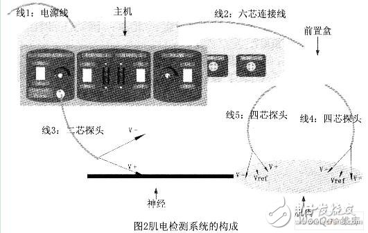
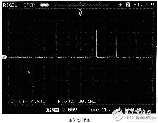
The manifestations of biological signals are diverse, such as changes in physical sound, light, electricity, force, etc.; and chemical concentrations, gas partial pressures, pH values, and the like. It is characterized by weak signal, non-linearity, high internal resistance, and many interference factors, which can reflect the living state of living organisms. Therefore, the collection and processing of biological signals is one of the important means of biological science research. The application direction of the biological nerve electrode amplifier system (hereinafter referred to as the myoelectric detection system) is to monitor the nerve regions of the brain during surgery. Although there are similar instrument systems at home and abroad, the domestic design is mostly limited. Among them, the part of the preamplifier lacks systemicity; while the foreign system has been formed, but it is expensive, and the subsequent processing of the signal has not been digitized. In comparison, the EMG detection system emphasizes systemicity, constitutes a complete instrument, and adopts a digital processing method, which provides space for future digital improvement of the system. At the same time, the cost of the system is about 2,000 yuan, while foreign products, such as Germany's Neurosign100, cost about 100,000 yuan, and the cost is greatly reduced. In addition, because it is self-developed, it has intellectual property rights. The application direction of the myoelectric detection system is to monitor the nerve regions of the brain during surgery. The method used is shown in Figure 1. First, a continuous neuron-like signal is generated at one end of the nerve, and the myoelectric signal is extracted from the muscle connected to the other end of the nerve for amplification, filtering, and the like, and finally displayed in the form of LED and sound. In real time, it is detected whether the nerve is encountered during the operation. Therefore, for the amplifier system to be designed, it is necessary to generate a neuro-electrical signal as a stimulation signal, and the biological signal to be amplified is an electromyogram signal. The nerve signal has the same characteristics as the other biological signals of the human body, and has its own unique features. According to neurobiology research, the neural signal is a pulse-like electrical signal with a frequency of about 1 kHz and a high frequency of 10 kHz. It should be a pulse current with a pulse width of 0.2 ms and a peak value of 0.05 mA to 1 mA. The frequency has two options: 3Hz and 30Hz. The myoelectric detection system includes a stimulation circuit, an amplification and filtering circuit, and a display processing circuit, and the electrodes are also designed, including probes, and the expected results are shown in FIG. The left side of Figure 2 is the excitation part of the electrical signal, which is used to stimulate the nerve. It can generate two current pulses of frequency 3Hz and 30Hz. The width of the pulse is 0.2ms, the peak value is adjustable between 0.05~5mA. The signal part is on the right. Used to process electrical signals generated by the receiving muscles. The specific parameter indicators of the signal processing and display prompt part are as follows: divided into two channels, which can display and indicate the intensity of the received EMG signal independently. The intensity of the myoelectric signal is displayed by LED light, ranging from 30 μV to 20 mV; the intensity of the myoelectric signal is indicated by a buzzer, and the volume is adjustable. The electrode receiving the EMG signal has three legs (V+), (Vref), and (V-) for use in the receiving and processing sections. 2.1 Stimulation circuit Since the output pulse current is required, there are two options of 3 Hz and 30 Hz, and the pulse width is 0.2 ms, and the pulse current is not easy to be directly generated. Therefore, the pulse pulse generating circuit first generates a voltage pulse at a frequency of 3 Hz and 30 Hz, and the pulse width is 0.2ms. Then, it is converted into a current pulse by a V/I conversion circuit, and the conversion circuit includes an adjustable knob, and the peak value of the control output pulse is between 0.05 and 5 mA. 2.2 pre-processing box circuit The EMG signal from the probe is first sent to the preamplifier circuit for voltage signal amplification, and then subjected to high-pass filtering to filter out the polarization voltage and low frequency noise. The low frequency cutoff frequency is 5 Hz (the polarization voltage is V+ of the probe). And the V-foot is inserted into the muscle to produce a different depth. The high-pass filtered voltage signal is then low-pass filtered to filter out high-frequency noise with a high-frequency cutoff frequency of 1 kHz. The low-pass filtered voltage signal is then subjected to a power frequency notch to filter out the electrical signal of the 50 Hz power frequency. At this point, the processing of the pre-processing cartridge is completed, and the processed voltage signal is used for the subsequent-stage signal processing and display prompting circuit. 2.3 signal processing and display prompt circuit The voltage signal output by the pre-processing box is first amplified to a suitable amplitude by a two-stage amplifier circuit, and then the LED is driven to display the intensity of the myoelectric signal. At the same time, the voltage signal is amplified and sent to the speaker circuit for sound prompting. In addition to the main circuit of the above-mentioned vines, it is necessary to have a power supply circuit and various interface circuits to complete an overall system. The power supply circuit is divided into the power supply of the excitation circuit and the front part of the isolator due to the different requirements of the power supply of each part of the circuit. The negative 15V power supply, the positive and negative 15V power supply after the isolator, the power supply of the A/D part, the power supply of the LED and the power supply of the speaker are five parts. After drawing on the PCB, we made the experiment board. Based on this experimental board, we conducted a variety of tests to verify the performance of the designed system. 3.1 Test of stimulation circuit (1) When the frequency selection terminal is set to a high level, the output voltage waveform of the 3 pin of the 555 timer is a pulse wave with a peak value of about 4.16V and a frequency of about 3.1 Hz; when the frequency selection terminal is set to a low level, the output is It is a pulse wave with a peak value of about 4.16V and a frequency of about 30 Hz. It is proved that the function of pulse voltage generation and frequency selection of the system works normally. (2) Select the frequency selection terminal to set a low level, and connect a 1kΩ load resistor to both ends of the output of the stimulation circuit, and simultaneously detect the voltage at both ends, and the waveform is as shown in Fig. 3. The peak value is about 4.64V, the frequency is still about 30Hz, the output current peak value is about 4.64mA, and the replacement load resistance is 300 Ω, the output waveform frequency is constant, and the peak value is about 1.39V, the current is obtained. The peak value is still about 4.64 mA, which proves that the voltage/current conversion function works normally, and when the pulse voltage is high, a constant current can be output. (3) When the load resistance is constant, change the variable resistance value in the voltage/current conversion circuit, and find that the peak value of the output waveform changes accordingly, because a current limit is connected to a 1k Ω before the variable resistor. The resistance, so the measured maximum current value is about 4.6mA, and the minimum value is about 0.04mA, so the selection function of the output current value in the design requirements can be realized by the variable resistor, and the adjustment range can be The maximum resistance of the current limiting resistor, current limiting resistor and variable resistor is limited. Summarize that the excitation signal is normal and has a constant peak pulse current. 3.2 Amplification circuit test The input frequency of the front box is input at a frequency of 100 Hz, and the peaks are 200 μV, 500 μV and 1 mV sine waves. The output waveform is tested step by step. When the amplifier is stably amplified, the total magnification of the front panel is about 100. 3.3 Test of the speaker circuit When the frequency selection terminal is set to a high level, that is, 3 Hz is selected, the output waveform of the speaker circuit is selectively cut off, and when the frequency selection terminal is set to a low level, that is, 30 Hz is selected, the waveform is continuous, so two types In the case of different sound effects; in any case, changing the variable resistance in the speaker circuit can change the peak value of the output waveform to change the volume of the output. Summarize the test results of the motherboard speaker control part: 1) The channel can be selected by a switch. 2) The frequency of the output sound can be controlled according to the operating frequency of the excitation signal (3 Hz / 30 Hz). 3) The volume of the output sound can be adjusted by an adjustable resistor. 4) The volume can be increased as the amplitude of the input signal increases. 3.4 Testing of other functional circuits (1) Power test results: The power supply works normally, output positive and negative 15 V power supply, so that the whole system can work normally. (2) Digital tube display circuit test result: display is normal. Through simulation and actual board test, it can be verified that the general function of the system has been completed, and the running performance is good. The specific parameters are as follows: 1) A pulse current with a frequency of 3 Hz or 30 Hz and a pulse width of 0.2 ms is generated, and the current peak is constant, and is adjustable at 0.04 to 4.6 mA; 2) The overall amplification gain of the system is between 960 and 100007; 3) The voice prompts that the volume becomes higher as the amplitude of the input signal increases, the channel can be selected by the switch, and the frequency of the output sound can be controlled according to the operating frequency of the excitation signal (3 Hz/30 Hz), and the volume of the output sound can be passed through a Adjustable resistance adjustment. The medical application of the myoelectric detection system has broad prospects, but since it will be directly applied to the human body, various performance requirements are strict. At present, the main body of the design and test of the system has been completed, and the running performance of the system is also relatively good, but there are still many places to be improved, such as the detection part of the stimulation circuit, the poor function of the power frequency trap circuit and so on. waiting for solution. In addition to this, the system has a wide range of improvements, such as: (1) The circuit structure currently uses analog circuits, but some of the modules, such as pulse source generation and filter circuits, can be digitally designed to make the structure more integrated; (2) The current application direction of the system is limited to the monitoring of the operation, but because of its large range of amplification gain, the application can be continuously expanded through the continuous improvement of details in the future, such as the number of signals collected by the system can be increased. It can be applied to the analysis of different biological signs, and the display data of the back end can be more complicated, so that the system can be applied to the monitoring of critically ill patients. Therefore, the project needs to put more efforts until the system is further improved to meet the requirements of practical medical treatment. This is the development prospect of the myoelectric detection system.
The sensor includes linear encoder and rotary encoder, which is used for the position measurement of speed, displacement and angle. Yuheng optics can provide rotary encoders based on optical, magnetic and gear principles, linear encoders based on optical principles and supporting products.
Custom Sensor,Clintegrity Encoder,Absolute Angle Encoder,Small Rotary Encoders Yuheng Optics Co., Ltd.(Changchun) , https://www.yhenoptics.com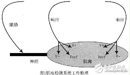

Design and testing of a biological nerve electrode amplifier system (electromyography system)
0 Preface