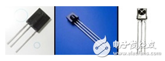
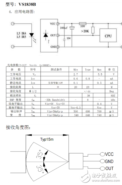
Photoelectric sensors are controlled by converting changes in light intensity into changes in electrical signals. Photoelectric sensors are generally composed of three parts, which are divided into: transmitter, receiver and detection circuit. The transmitter is aimed at the target emitting beam, and the emitted beam is generally derived from a semiconductor light source, a light emitting diode (LED), a laser diode, and an infrared emitting diode. The beam is emitted uninterrupted or the pulse width is varied. The receiver is composed of a photodiode, a phototransistor and a photocell. In front of the receiver, optical components such as lenses and apertures are mounted. Behind it is a detection circuit that filters out the valid signal and applies the signal. In addition, the structural components of the photoelectric switch also include a launching plate and an optical fiber. The triangular reflector is a structurally sound launcher. It consists of a small triangular pyramidal reflective material that enables the beam to be accurately returned from the reflector, which is practical. It can change the emission angle in the range from 0 to 25 with the optical axis, so that the beam returns from almost one emission line, after reflection, or from this reflection line. (1) slot type photoelectric sensor Mounting a light emitter and a receiver face to face on either side of a slot is a trough optoelectronic. The illuminator emits infrared or visible light, and the optical receiver can receive light in an unobstructed condition. However, when the object to be detected passes through the slot, the light is blocked and the photoelectric switch operates. A switch control signal is output to cut or turn on the load current to complete a control action. The detection distance of the slot switch is usually only a few centimeters due to the limitation of the overall structure. (2) Optotype photoelectric sensor If the illuminator and the illuminator are separated, the detection distance can be increased. A photoelectric switch composed of an illuminator and a light collector is called an off-beam split type photoelectric switch, and is simply referred to as an on-beam type photoelectric switch. Its detection range can be several meters or even tens of meters. In use, the illuminator and the light receiver are respectively mounted on both sides of the path of the detection object, and when the detection object passes, the light path is blocked, and the light receiver outputs a switch control signal. (3) Reflective type photoelectric switch A reflector-reflective (or mirror-reflective) photoelectric switch is installed in which the illuminator and the illuminator are housed in the same device, a reflector is placed in front of it, and the photoelectric control function is performed by the reflection principle. Under normal circumstances, the light emitted by the illuminator is reflected by the reflector and received by the light receiver; once the light path is blocked by the object, and the light receiver receives no light, the photoelectric switch operates to output a switch control signal. (4) Diffuse reflective photoelectric switch Its detector head is also equipped with an illuminator and a light receiver, but there is no reflector in front. Under normal circumstances, the light collector emitted by the illuminator cannot be found. When the detection object passes, the light is blocked, and the light is partially reflected back, and the light receiver receives the light signal and outputs a switching signal. The infrared receiving head is generally a receiving, amplifying and demodulating integrated head. After the infrared signal is demodulated by the receiving head, the difference between the data “0†and “1†is usually reflected in the high or low time length or signal period, and the single chip decoding When the receiver output pin is usually connected to the external interrupt of the microcontroller, the timer is used to determine the time of the external interrupt interval to obtain data. The point is to find the difference in waveform between the data "0" and "1". The infrared receiving head of the three legs is generally a receiving, amplifying and demodulating integrated head, and the output of the receiving head is a demodulated data signal (specific signal format, search "infrared signal format", a large number), the need for the single chip The corresponding reading program. Infrared communication uses infrared technology to achieve close-range secure communication and information forwarding between two points. It is generally composed of two parts, an infrared transmitting and receiving system. The transmitting system modulates an infrared radiation source to emit an infrared signal, and the receiving system receives the optical device and the infrared detector to form an infrared communication system. Let me talk about what is infrared. We know that the visible light that people can see is arranged in wavelength from long to short, followed by red, orange, yellow, green, cyan, blue, and purple. The wavelength range of red light is 0.62 to 0.76 μm; the wavelength range of violet light is 0.38 to 0.46 μm. Light that is shorter than the wavelength of violet light is called ultraviolet light, and light that is longer than the wavelength of red light is called infrared light. Infrared remote control uses a near infrared ray with a wavelength between 0.76 and 1.5 μm to transmit control signals. Commonly used infrared receivers have the following shapes: IRM138S Series IRM338 IRM38A Series IRM38B Series Please download here for the specification: Infrared Receiver Specification Infrared remote control system Commonly used infrared remote control systems generally divide and transmit two parts. The main component of the transmitting portion is an infrared light emitting diode. It is actually a special light-emitting diode. Because its internal material is different from ordinary light-emitting diodes, it emits infrared light instead of visible light when a certain voltage is applied across it. The infrared light-emitting diodes currently used in large quantities emit infrared light with a wavelength of about 940 nm, and have the same shape as ordinary light-emitting diodes, but with different colors. Infrared light-emitting diodes are generally available in black, dark blue, and transparent colors. The way to judge whether the infrared light-emitting diode is good or bad is the same as judging the ordinary diode: use the multimeter to block the positive and negative resistance of the infrared light-emitting diode. The luminous efficiency of infrared light-emitting diodes can be accurately determined by special instruments, and in the amateur conditions, only the pull distance method can be used for rough determination. The infrared receiving tube of the receiving portion is a photodiode. In practical applications, the infrared receiving diode should be reverse biased, so that it can work normally, that is, the infrared receiving diode is reversely applied in the circuit, so that high sensitivity can be obtained. Infrared receiving diodes are generally available in both circular and square shapes. Since the transmitting power of the infrared light emitting diode is generally small (about 100 mW), the signal received by the infrared receiving diode is relatively weak, so it is necessary to increase the high gain amplifying circuit. In the past few years, the μPC1373H, CX20106A and other infrared receiving special amplification circuits have been commonly used. In recent years, whether it is amateur production or formal products, most of them use finished infrared receivers. There are roughly two types of finished infrared receivers: one with metal shield and one with plastic. There are three pins, power positive (VDD), power (GND), and data output (VO or OUT). The pin arrangement of the infrared receiver is different depending on the model. Refer to the manufacturer's instructions. The advantage of the finished infrared receiver is that it does not require complicated debugging and shielding of the outer casing. It is very convenient to use like a triode. However, pay attention to the carrier frequency of the finished infrared receiver when using. The commonly used carrier frequency for infrared remote control is 38 kHz, which is determined by the 455 kHz crystal used by the transmitter. At the transmitting end, the crystal is divided by an integer. The division factor is generally 12, so 455 kHz ÷ 12 ≈ 37.9 kHz ≈ 38 kHz. There are also some remote control systems that use 36 kHz, 40 kHz, 56 kHz, etc., which are generally determined by the oscillation frequency of the crystal of the transmitting end. The feature of infrared remote control is that it does not affect the surrounding environment and does not interfere with other electrical equipment. Because it can't penetrate the wall, the household appliances in different rooms can use the universal remote control without mutual interference; the circuit debugging is simple, as long as the connection is given according to the given circuit, generally no work is required to be put into operation; codec Easy, multi-channel remote control is available. Since each manufacturer produces a large number of infrared remote control ASICs, you can press the map as needed. Therefore, infrared remote control has been widely used in home appliances and indoor close-range (less than 10 meters) remote control. The multi-channel infrared transmitting section typically has a number of buttons that represent different control functions. When the transmitter presses a button, there are different output states at the receiver end. The output state of the receiving end can be roughly divided into five forms: pulse, level, self-locking, interlocking, and data. The “pulse†output is when the transmitter pushes the button, the receiver outputs an “effective pulse†corresponding to the output, and the width is generally about 100ms. The “level†output means that when the transmitter presses the button, the receiver outputs the “active level†corresponding to the output. When the transmitter releases the button, the “active level†of the receiver disappears. The "effective pulse" and "active level" here may be high or low, depending on the static condition of the corresponding output pin. For example, if the static is low, "high" is valid; if it is static, it is high. , then "low" is valid. In most cases "high" is valid. The “self-locking†output refers to the fact that each time the transmitting end presses a certain key, the receiving end changes its state correspondingly to the output end, that is, the original high level becomes the low level, and the original level is the low level. This output is suitable for use as a power switch, mute control, and the like. Sometimes this output form is called "inverted". The “interlock†output means that multiple outputs are cleared from each other, and only one output is valid at the same time. This is the case for the TV station selection, such as dimming, speed control, and audio input selection. The "data" output refers to the numbering of some of the transmitting keys, and the use of several outputs of the receiving end to form a binary number to represent different key inputs. Under normal circumstances, in addition to several data output, the receiving end should also have a "data valid" output, so that the latter stage can take data in a timely manner. This form of output is typically used to interface with a microcontroller or microcomputer. In addition to the above output forms, there are two forms of "latch" and "temporary storage". The so-called "latch" output refers to the signal sent to the transmitting end each time, the corresponding output of the receiving end is "stored" until a new signal is received; the "temporary memory" output is similar to the "level" output described above.
Shenzhen Guan Chen Electronics Co., Ltd. is a High-tech enterprise that
integrates R&D, design, manufacture of computer peripheral products.The
products include Thunderbolt Docking Station,USB Docking Station,USB Hubs,USB
Adapter, Thunderbolt Cable , SSD Enclosure , HDD Enclosure . Our company adheres to
the principle and motto of Being sincere, Responsible, Practical to meet the
needs of markets and customers with high quality technology and management. We
commit ourselves to new product development and also stress the exploring of
international markets.
Our company owns a professional production team and establishes strict
quality control standard, so we can provide high quality products and service
for customers. We have Grapgic designer,3D Deisnger and Electronic designer to
provides professional OEM/ODM service. Our factory covers an area of 1,000-2000
spare meters, which houses 100-200 workers, so our production capacity reaches
50,000 pieces every day.With more than 10 engineers focusing on research and
development, our private model attracts much among different markets. Over 100
new designed models are released per year.There are also 3 lean production
lines to fullfill small quatity orders production for variety of models.
Our Thunderbolt 3 Docking Station has passed thunderbolt certified by
intel and apple.Our product also all can meet with CE, RoHS, UL, FCC and other
related certification.And our factory also meets legal environmental standards
ensuring your order is delivered. We have a very good reputation at home and
abroad. Our products are mainly exported to Europe, USA and Southeast Asia. We
provide one-stop-service and promote customers achieve rapidly development.
Customer comes First, Quality Ranks First, and Reasonable Price.Guanchen will
be your faithful partner from China.
Ngff Ssd Enclosure,M.2 Ngff Ssd Enclosure,Type-C Ngff M.2 External Ssd Enclosure,Ngff External Ssd Enclosure Shenzhen GuanChen Electronics Co., Ltd. , https://www.gcneotech.com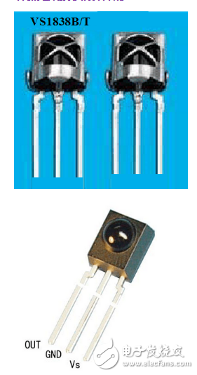
Detailed description of the types and working principles of photoelectric sensors
The type of photoelectric sensor The working principle of photoelectric sensor (the principle of infrared photoelectric sensor)