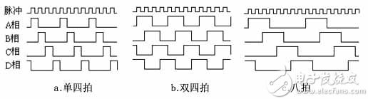
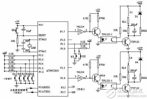
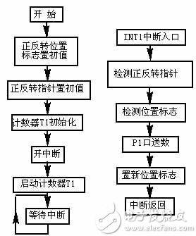
Stepper motors have a wide range of applications in control systems. It can convert pulse signals into angular displacements and can be used as electromagnetic brake wheels, electromagnetic differentials, or angular displacement generators. Sometimes stepper motors that are removed from some old equipment (which are generally not damaged) should be used for other purposes. Generally, you need to design your own drive. This article describes the driver designed for a stepper motor that was removed from a Japanese-made printer. This article first introduces the working principle of the stepper motor, and then introduces the software and hardware design of its driver. 1. Working principle of stepper motor The stepping motor is a four-phase stepping motor and is powered by a unipolar DC power supply. As long as the phase windings of the stepper motor are energized at the appropriate timing, the stepper motor can be stepped. FIG. 1 is a schematic diagram of the working principle of the four-phase reaction type stepping motor. Figure 1 Four-phase stepper motor step diagram At the beginning, the switch SB is turned on, SA, SC, and SD are disconnected, and the B-phase magnetic poles are aligned with the rotors 0 and 3, and the teeth of the rotors 1 and 4 and the magnetic poles of the C and D phase windings are misaligned. 2, the 5th tooth and the D, A phase winding magnetic poles produce wrong teeth. When the switch SC is turned on and the SB, SA, and SD are turned off, the rotor rotates due to the action of the magnetic lines of the C-phase winding and the magnetic lines between the No. 1 and No. 4 teeth, and the magnetic poles of the No. 1, No. 4 and C-phase windings are aligned. . The 0th and 3rd teeth and the A and B phase windings produce the wrong teeth, the 2nd and 5th teeth and the A and D phase winding magnetic poles. The four-phase stepping motor can be divided into three working modes: single four-shot, double four-shot, and eight-shot according to the order of power-on. The step angle of the single four-shot and the double-four beat is equal, but the turning moment of the single four-shot is small. The step angle of the eight-shot working mode is half of the single-four-shot and double-four-shot. Therefore, the eight-shot working mode can maintain a high rotational torque and improve the control accuracy. The power-on timing and waveform of the single four-shot, double four-shot and eight-shot modes are shown in Figure 2.a, b, and c, respectively: Figure 2. Stepper motor operation timing waveform 2. Circuit principle of stepping motor driver system based on AT89C2051 Figure 3 Stepper motor driver system circuit schematic AT89C2051 outputs the control pulse from P1.4 to P1.7 of P1 port, and then enters 9014 after being inverted by 74LS14. After 9014 amplification, the photoelectric switch is controlled. After photoelectric isolation, the pulse signal is amplified by voltage and current by power tube TIP122. Drive the phase windings of the stepper motor. The stepping motor is rotated, reversed, accelerated, decelerated, and stopped with different pulse signals. In the figure, L1 is a phase winding of a stepping motor. The AT89C2051 selects a crystal oscillator with a frequency of 22MHz. The purpose of selecting a higher crystal oscillator is to minimize the influence of the AT89C2051 on the pulse signal period of the host computer in mode 2. In Figure 3, RL1 to RL4 are the internal resistance of the winding, and the 50Ω resistor is an external resistor that acts as a current limiting device and is also an element that improves the circuit time constant. D1~D4 are freewheeling diodes, so that the back electromotive force generated by the motor windings is attenuated by the freewheeling diodes (D1~D4), thereby protecting the power tube TIP122 from damage. Parallel connection of a 200μF capacitor on a 50Ω external resistor improves the current pulse front edge injected into the stepper motor winding and improves the high frequency performance of the stepper motor. The 200Ω resistor in series with the freewheeling diode can reduce the discharge time constant of the loop, make the trailing edge of the current pulse in the winding steep, reduce the current drop time, and also improve the high frequency performance. 3. Software design The driver has three working modes to choose according to different combinations of the DIP switches KX and KY: Mode 1 is the interrupt mode: P3.5 (INT1) is the step pulse input terminal, and P3.7 is the forward and reverse pulse input terminal. The host computer (PC or MCU) and the driver are connected by only 2 lines. Mode 2 is the serial communication mode: the host computer (PC or MCU) sends the control command to the driver, and the driver completes the relevant control process according to the control command. Mode 3 is the dial switch control mode: the stepper motor is directly controlled by different combinations of K1 to K5. When power is turned on or the reset button KR is pressed, the AT89C2051 first detects the state of the DIP switches KX and KY, and enters different working modes according to different combinations of KX and KY. The program flow diagram and source program of Mode 1 are given below. In the preparation of the program, special attention should be paid to the processing of the stepping motor during commutation. In order to make the stepper motor smooth transition during commutation, and not to generate a wrong step, the flag should be set in each step. Among them, the 20H unit is the stepping motor forward rotation flag; the 21H unit is the reverse flag. In the forward rotation, not only the forward flag flag is assigned, but also the inversion flag bit is assigned; this is also the case when inverting. In this way, when the stepping motor is reversed, the last position can be used as the starting point to reverse the movement, which avoids the wrong step when the motor is commutated. Figure 4 Mode 1 block diagram Mode 1 source program: MOV 20H, #00H ; 20H unit initial value, motor forward position pointer MOV 21H, #00H ; 21H unit initial value, motor reverse position pointer MOV P1, #0C0H ; P1 port initial value to prevent motor short circuit MOV TMOD, #60H ;T1 counter initial value, open interrupt MOV TL1, #0FFH MOV TH1, #0FFH SETB ET1 SETB EA SETB TR1 SJMP $ ;***********Counter 1 interrupt program ************** IT1P: JB P3.7, FAN; motor forward and reverse pointer ;*************The motor is turning ***************** JB 00H, LOOP0 JB 01H, LOOP1 JB 02H, LOOP2 JB 03H, LOOP3 JB 04H, LOOP4 JB 05H, LOOP5 JB 06H, LOOP6 JB 07H, LOOP7 LOOP0: MOV P1, #0D0H MOV 20H, #02H MOV 21H, #40H AJMP QUIT LOOP1: MOV P1, #090H MOV 20H, #04H MOV 21H, #20H AJMP QUIT LOOP2: MOV P1, #0B0H MOV 20H, #08H MOV 21H, #10H AJMP QUIT LOOP3: MOV P1, #030H MOV 20H, #10H MOV 21H, #08H AJMP QUIT LOOP4: MOV P1 , #070H MOV 20H, #20H MOV 21H, #04H AJMP QUIT LOOP5: MOV P1, #060H MOV 20H, #40H MOV 21H, #02H AJMP QUIT LOOP6: MOV P1, #0E0H MOV 20H, #80H MOV 21H, #01H AJMP QUIT LOOP7: MOV P1, #0C0H MOV 20H, #01H MOV 21H, #80H AJMP QUIT ;***************Motor reversal***************** FAN: JB 08H, LOOQ0 JB 09H, LOOQ1 JB 0AH, LOOQ2 JB 0BH, LOOQ3 JB 0CH, LOOQ4 JB 0DH, LOOQ5 JB 0EH, LOOQ6 JB 0FH, LOOQ7 LOOQ0: MOV P1, #0A0H MOV 21H, #02H MOV 20H, #40H AJMP QUIT LOOQ1: MOV P1, #0E0H MOV 21H, #04H MOV 20H, #20H AJMP QUIT LOOQ2: MOV P1, #0C0H MOV 21H, #08H MOV 20H, #10H AJMP QUIT LOOQ3: MOV P1, #0D0H MOV 21H, #10H MOV 20H, #08H AJMP QUIT LOOQ4: MOV P1, #050H MOV 21H, #20H MOV 20H, #04H AJMP QUIT LOOQ5: MOV P1, #070H MOV 21H, #40H MOV 20H, #02H AJMP QUIT LOOQ6: MOV P1, #030H MOV 21H, #80H MOV 20H, #01H AJMP QUIT LOOQ7: MOV P1, #0B0H MOV 21H, #01H MOV 20H, #80H QUIT: RETI END 4 Conclusion The driver has been experimentally proven to drive a 0.5Nm stepper motor. Adjust the parameters of the resistor, capacitor and freewheeling diode of the drive part to drive a 1.2Nm stepper motor. The driver circuit is simple and reliable, and has a compact structure. It is especially suitable for systems with I/O lines and microcontroller resources. This smart battery charger is equipped with a selector which allows you to set the charger for charging SLA/GEL/AGM/Flooded/ Calcium lead-acid batteries and LiFePO4 batteries. The smart battery charger can be used as a constant power supply to run accessories that require astable and clean dc voltage. 12V battery charger, lithium battery charger,Battery Charger, Solar Charge Controller Hangzhou Saintish Technology Co.,Ltd. , https://www.saintishtech.com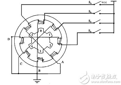
Produce wrong teeth. By analogy, the four-phase windings of A, B, C, and D are alternately powered, and the rotor will rotate in the A, B, C, and D directions.