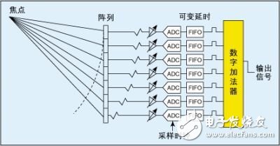
Ultrasound systems are one of the most sophisticated signal processing instruments currently in widespread use. Like any complex instrument, there are many trade-offs to achieve due to performance, physical, and cost requirements. Mastering some system-level knowledge is necessary to fully understand the functional and performance levels of the required front-end ICs, especially low noise amplifiers (LNAs), time gain compensation amplifiers (TGCs, a variable gain amplifier), and analog-to-digital conversion. (ADC). These analog signal processing ICs are key factors in determining the overall performance of the system. The characteristics of the front-end ICs dictate the limits of system performance, and once noise and distortion are introduced, it is virtually impossible to remove them. In all ultrasound systems, a multi-sensor array is placed at the end of a relatively long cable (approximately 2 m) containing 48 to 256 core micro-coaxial cables. High speed (HV) multiplexers or demultiplexers are used in some arrays to reduce the complexity of the transmit and receive hardware, but at the expense of flexibility of use. The most flexible systems used are phased array digital beamformer systems - they are also often the most costly systems because of the need to achieve full electronic control of all channels. However, front-end ICs such as the AD8332 dual variable gain amplifier (VGA) and the AD8335 quad VGA and the AD9229 12-bit quad analog-to-digital converter are driving down cost and power per channel, making even low-cost systems It is possible to achieve full electronic control of all channels. At the transmit (Tx) side, the Tx beamformer first determines the delay mode in which the desired transmit focus is set, and then amplifies the output of the beamformer with the high voltage transmit amplifier that drives the sensor. On the receive (Rx) side, there is a Transceiver (T/R) switch, which is typically a diode rectifier bridge that isolates high voltage Tx pulses, followed by an LNA and one or more VGAs. Figure 1: Basic block diagram of the DBF system After amplification, analog beamforming (ABF) or digital beamforming (DBF) is completed. In addition to continuous wave (CW) Doppler processing, the dynamic range is too large to be processed with imaging channels, and most of the current systems are DBF. Finally, the Rx beam is processed to display grayscale images, two-dimensional color images, and/or color Doppler outputs. The purpose of the ultrasound system is to first give an accurate image of the internal organs of the human body, and the second is to determine the blood flow movement in the body by Doppler signal processing. The following is an analysis of the technical challenges in signal attenuation, power consumption, and dynamic range of the ultrasound system to achieve these goals, as well as the choice considerations for front-end ICs. 1 signal attenuation problem The ultrasound system has three main acquisition modes: B mode (grayscale imaging, 2D), F mode (Colorflow imaging or Doppler imaging, blood flow detection), and D mode (spectral Doppler). Medical ultrasound operates at frequencies from 1MHz to 40MHz, and external imaging typically uses 1MHz? The 15MHz frequency range, while the venous instrument uses a frequency of up to 40MHz. For a given penetration distance, tissue attenuation attenuates the signal frequency. The signal experiences an attenuation of approximately 1 dB/cm/MHz, ie for a 10 MHz signal and a penetration depth of 5 cm, the round-trip signal is attenuated by 5 & TImes; 2 & TImes; 10 = 100 dB. This poses a serious challenge for large dynamic range received signals: one problem is that the receiving circuit must have both low noise and large signal processing capability, and another important issue is the requirement for fast overload recovery. Even the T/R switch should prevent the receiver from receiving large pulses, a small portion of which leaks from the switch and is sufficient to overload the receiver. Poor overload recovery will put the receiver in a "blind" state until it recovers, which has a direct impact on the distance of the generated image from the skin surface. 2 ABF and DBF systems In analog ABF and DBF ultrasound systems, the channels are first delayed or stored for reception pulses reflected from a particular focus along the beam, then time-ordered, and their coherence is summed - this provides spatial processing gain because of the channel The noise is uncorrelated and the signal is correlated; this produces a theoretical processing gain of 10*log(N), where N is the number of channels. Images can be formed in two ways: one is to use analog sequence values ​​that simulate delay line delays, sum them and convert them to digital values ​​(ABF) after summation; the other is by approaching the sensor as close as possible The analog values ​​of the array elements are digitally sampled, stored in memory (FIFO), and then digitally summed (DBF). The figure shows the basic block diagram of a DBF system in which the ADC and FIFO are replaced by variable delay lines in the ABF system. Both systems require excellent channel-to-channel matching. It should be noted that both systems require VGA implementation, while the ABF system requires only a high resolution and relatively low speed ADC (downconverting the signal after summation), but DBF systems require many high speed, high resolution ADC because it is sampling the radio frequency (RF) bandpass signal. Pipeline Oil Contamination Detection Sensor This decice is installed in the cooling water line of ship and is designed to detect oil in cooling water.This system consists of oil detection pot,capacitive compact switch and control unit.Oil detection pot for separating oil and water has not cock valve for isolating the input and output line.Capacitive Type Oil Detector is installed in oil detection pot for separating oil and water has not cock valve for isolating the input and output line.Capacitive type oil detection pot,detecting oil Isolated form water on the top of oil detection pot.Control unit receive whether it is deteted or not in signal from the capaciteve compact switch and convert point of contact to relay contact. Pipeline Oil Contamination Detection Sensor,New Ss Oil Pressure Sensor,Oil Pressure Sensor,Ss Oil Pressure Sensor Taizhou Jiabo Instrument Technology Co., Ltd. , https://www.jbcbyq.com