Automotive Diagnostic Connectors And Cables
We make OBD connector with terminal by ourselves, soldering type and crimping type are both available. Such as 16pin obd connector. OBD1, OB2, J1939, J1708, J1962, etc. Also molded by different type, straight type or right-angle type. The OBD connector cables used for Audi, Honda, Toyota, BWM, etc. We have wide range of materials source , also we can support customers to make a customized one to replace the original ones.
Automotive Diagnostic Connectors And Cables,Obd Connectors,Reliable OBD Connector,Black OBD Connector,OBD Diagnostic Cable,OBD2 Connectors ETOP WIREHARNESS LIMITED , https://www.etopwireharness.com
CY7C68013 integrates an enhanced 8051 microcontroller and I2C compatible controller, and its transmission rate can reach 100 kHz or 400 kHz. LabVIEW is a software for designing virtual instruments based on a graphical language. LabVIEW uses a graphical block diagram to construct program code. LabVIEW programs are driven by data streams, which control the execution order of the programs. LabVIEW is powerful, it has a universal programming system with extensible function library and subroutine library, and its VISA (VIRtual INStrument Software Architecture) is an advanced application programming interface (API) used to communicate with various instrument buses. Limited by platform, bus and environment.
I2C (Inter-Integrated Circuit) bus is a two-wire serial bus developed by Philips, which is mainly used to connect microcontrollers and peripheral devices. It consists of data line SDA and clock SCL, used to send and receive data. Its main advantage is simplicity and effectiveness.
In general, the software of a complete USB communication system usually needs three parts: upper computer program, driver program and firmware program.
1 PC program development
Adopt LabvIEW of NI Company to realize the development of the upper computer program, and the control transmission method can be adopted during the development. In the control transmission, the function "VISA open" is used to open the specified USB device, and the "VISA USB control output" function is used to complete the definition request 0xBl, which can write the data in the "write buffer" to the FPGA register. Use the function "VISA USB control input" to complete the custom request 0xB2, and read the data in the FPGA register back to the "read buffer". Its block diagram is shown in Figure 1. 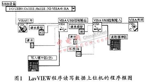
When the waveform is set to the host computer program, the function of generating a pop-up window can be used to set the program channel, and the event structure, case structure, and loop structure can realize the sub-VI generated by the arbitrary waveform; the case structure can realize six kinds SubVI design for basic waveform settings.
2 Driver development
NI VISA can be used to develop the driver during design. When performing USB communication, VISA provides two types of functions for LabVIEW to call, namely USB INSTR device and USB RAW device. A USB INSTR device is a USB device that conforms to the USBTMC protocol. When using a USB INSTR-type function, its communication does not need to be configured with NI-VISA; a USB RAW device refers to any USB device other than an instrument that clearly conforms to the USBTMC specification. You must configure NI-VISA. For detailed steps and procedures for configuring NI-VISA, refer to the free document "Using NI-VISA to Control USB Devices" on NI *****.
3 firmware program development
There are about five files that need to be modified to constitute the construction. Among them, Fw.c is the main file of the USB firmware program. In order to achieve control transmission, the file needs to be modified: one is to declare two functions for responding to the request of the custom device, and the second is to set the response part of the request of the custom device .
Periph. c First of all, the initialization function TD_Init (void) must be set, and the registers related to EPOBUF, the clock frequency of the CPU and the registers related to I2C should be set: secondly, the function used to respond to the request of the custom device must be defined.
Fx2. The custom request should be defined in the h header file.
Dscr. What needs to be set in a51 is the device descriptor and configuration descriptor, as well as the interface descriptor. The O endpoint required for control transmission does not need to be set.
Syncdly. Set the register of the initialization function TD_Init (void) in h.
The read and write functions of the I2C bus to be used in the examples introduced in this article are as follows:
The first is: EZUSB_WriteI2C (BYTE addr, BYTE length, BYTE xdata * dat), where addr is used to specify the I2C device address; length is the length of the transmitted data; * dat is the starting address of the send data buffer: this function can be used -USB I2C interface to write a string of data. This function returns immediately before all the provided data is sent. If data is currently being sent or received, FALSE is sent back, and the data is not sent. If the port is not busy, the data enters the queue and returns TRUE.
The second function is EZUSB_ReadI2C (BYTE addr, BYTE length, BYTE xdata * dat), where addr specifies the I2C device address; length is the length of the transmitted data; * dat is the start address of the receive data buffer; -USB I2C interface to read a string of data. The function returns immediately before all requested data is read into the buffer. The user needs to constantly ask the status of I2C to determine when the data is valid. If data is currently being sent or received, FALSE is returned when the function is called, and the data is not read. When the I2C port is not busy, the data queue is read and TRUE is returned.
The response program code for the custom request is given below: 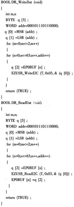
4 Conclusion
It mainly introduces the components and design process based on EZ-USBFX2 communication. This design uses NI LabVIEW as the setting data transmission part of the test system signal source, and achieves the purpose of configuring the signal source through the UCY7C-68013 chip program. The communication process has now passed the NI company's VISAInteracTIve Control software test. In fact, in addition to the configuration function, the USB chip can also use other resources to conveniently achieve the test data transmission of the test system, so as to achieve the purpose of making full use of resources.
Development and design of USB communication program using CY7C68013A
0 Preface