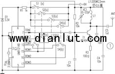
The following is the circuit diagram of [DTMF signal wireless remote control circuit ] DTMF signal wireless remote control circuit Wireless remote control circuit This section introduces the use of radio frequency signals to remotely control various electrical circuits. The number of remote control channels is 4, and can be extended to 12 when needed. It uses the DTMF (Dual Tone Multi-Frequency) signal in the telephone as the control code to modulate the carrier frequency of about 100 MHz, and then sends it out with the antenna. The receiving circuit uses a frequency modulation receiver to demodulate the signal into a DTMF signal, which in turn is connected to a DTMF/BCD converter and converted into a BCD output for controlling the turning on and off of the 4-way electrical device. The remote transmitter (see Figure 1) consists of a DTMF generator and an FM transmitter circuit. Here, the circuit for remotely controlling various electrical appliances using radio frequency signals is introduced. The number of remote control roads is 4, and can be extended to 12 when needed. It uses the DTMF (Dual Tone Multi-Frequency) signal in the telephone as the control code to modulate the carrier frequency of about 100 MHz, and then sends it out with the antenna. The receiving circuit uses a frequency modulation receiver to demodulate the signal into a DTMF signal, which in turn is connected to a DTMF/BCD converter and converted into a BCD output for controlling the turning on and off of the 4-way electrical device. The remote transmitter (see Figure 1) consists of a DTMF generator and an FM transmitter circuit. Here, a UM91214B telephone-specific IC is used to generate the DTMF signal, and its 3V power supply voltage is supplied from the 9V battery through the 3V Zener D1. The circuit uses a 3.58MHz crystal as the time base circuit. The {12} and {15} pins of IC1 are the first column and the first leg respectively. They are short-circuited through the switch S1(b). At this time, the DTMF of the {7} pin output. The signal (sound) is equivalent to the dual tone multi-frequency signal sent by the telephone number 1 key. Similarly, {13}, {16}, and {17} are the second column and the second and third legs, respectively, in {13}{15}, {13}{17}, {12}{16} respectively. When short-circuited with S2(b), S3(b), and S4(b), the signal output from the {7} pin is equivalent to the dual-tone multi-frequency signal sent by the 2nd, 4th, and 8th keys of the telephone. The remaining feet of IC1 are used as they are. The transmitter circuit is composed of a transistor T1 and its peripheral circuits. The tuning circuits L1 and VC1 are tuned near the carrier frequency of 100 MHz, and the antenna is equipped with a whip antenna, which is 10 cm to 15 cm long, and the control range is quite good. The DTMF signal is sent from the {7} pin of IC1 to the base of T1 and then transmitted outward by the antenna ANT. The receiving portion (see Fig. 2) is composed of the DTMF/BCD conversion chip IC2 of the FM receiver and a set of four trigger latch circuits IC3, IC4. The FM DTMF signal is first converted to a BCD signal by IC2 after demodulation by the FM receiver. At this time, the digital "1" is 0001, the digital "4" is 0100...etc., and IC2 also works with a 3.58MHz crystal. The BCD signals are sent from the {11}~{14} pins to the four D-trigger latches. The four D flip-flops are provided by two dual-D flip-flop chips (CD4013B), "1", "2", " When any one of the 4" and "8" keys is pressed, a signal input end of a D flip-flop corresponding to the key is fed, so that the output state of the D flip-flop is reversed, thereby driving the related The transistor and the corresponding relay act as a pull-in and release action, thereby turning the appliance controlled by the relay on or off. Since the UM91214B can generate a total of 12 DTMF signals, simply increase the number of control buttons in the transmitter circuit and add a 4/16 line converter between the IC2 and D flip-flops in the receiving part. By increasing to 12, you can control the switching of 12 electrical appliances.
ZGAR bar 2000 Puffs
ZGAR electronic cigarette uses high-tech R&D, food grade disposable pod device and high-quality raw material. All package designs are Original IP. Our designer team is from Hong Kong. We have very high requirements for product quality, flavors taste and packaging design. The E-liquid is imported, materials are food grade, and assembly plant is medical-grade dust-free workshops.
Our products include disposable e-cigarettes, rechargeable e-cigarettes, rechargreable disposable vape pen, and various of flavors of cigarette cartridges. From 600puffs to 5000puffs, ZGAR bar Disposable offer high-tech R&D, E-cigarette improves battery capacity, We offer various of flavors and support customization. And printing designs can be customized. We have our own professional team and competitive quotations for any OEM or ODM works.
We supply OEM rechargeable disposable vape pen,OEM disposable electronic cigarette,ODM disposable vape pen,ODM disposable electronic cigarette,OEM/ODM vape pen e-cigarette,OEM/ODM atomizer device.
Disposable Vape, bar 2000puffs, ZGAR bar disposable, Disposable E-cigarette, OEM/ODM disposable vape pen atomizer Device E-cig ZGAR INTERNATIONAL TRADING CO., LTD. , https://www.zgarette.com