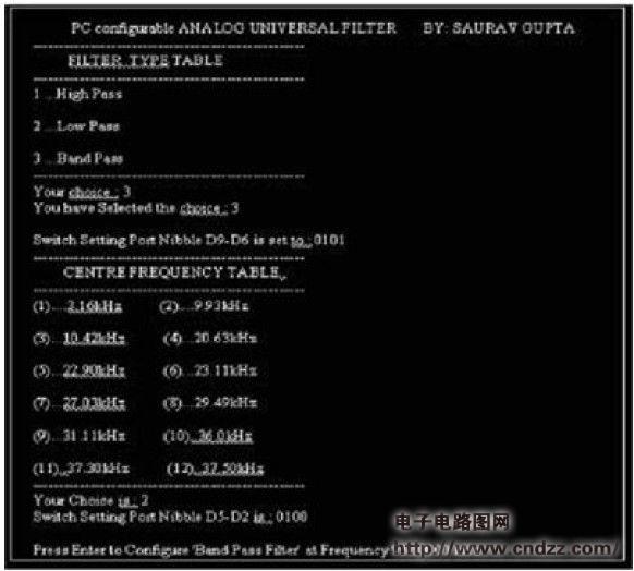
description: In this "Design Example" section, a general-purpose filter circuit for low-power instruments can be programmed on a PC using a parallel port. This filter circuit uses digital potentiometers and uses analog switches and latches for digital control (Figures 1 and 2). By running simple software code on your PC, you can configure a reliable design that can be used as a low pass filter, high pass filter or band pass filter, and also select the desired center frequency ω0 (Table 1) ). Unlike a similar controllable design (Reference 1), this design is a filter with only one output at a time. Many power-sensitive systems do not require simultaneous filtering. The argument for this design is that the series RLC resonator can provide different filtering functions through its components. Since this design is based on RLC components, it is not important to convert it to a PC controlled resonator. In Figure 1, the inductor LP is implemented as a PC-controlled composite inductor with an inductance value of LP = C2RPR3R5/R2. In the formula, RP can take any of 15 inductance values, depending on the state of switches S1~S4 (determined by PC port data bits D2~D5). The frequency formula is ω0 = (R2 / C1RPR3R5) 1/2. This way, you can choose 15 valid frequency values. (This design uses 12 practical frequency values). Data bits D6~D9 from the PC parallel port are used to set the analog switches S5~S8. The state of these switches determines the type of filter. Figure 1. A PC-configurable filter uses a composite inductor and several analog switches to determine the filter type and center frequency. Figure 2 You must consider the limited on-resistance of the analog switch when determining the center frequency of the filter. Figure 3 shows a display of the circuit generated by the software. This design uses a 9.93 kHz bandpass filter for demonstration and testing. Increase the number of analog switches to widen the frequency range. In addition, you can use additional switches to gain gain programmability. The 74573 latch has an interface to the PC. Table 1 shows the port/switch settings corresponding to some frequency and filter type selections. It is worth noting that the analog switch (DG308) has a finite operational on-resistance of approximately 110 Ω; this resistance must be taken into account when calculating the center frequency. Figure 3 The user-friendly configuration screen determines the filter type and frequency. Source address of this article: Gunnpod Disposable Vape Device is the hot sale vape in Australia market. The Gunnpod 2000 Puffs battery is 1250 Mah with a 8 ml tank, With strong power of battery and big capacity, the gunnpod can reach up to 2000 puffs, it can last for several days, flavor is variety, from classic tobacco to grape, gunnpod 2000 puffs can meet you with different flavor vaping require! Gunnpod 2000 Puffs,Gunnpod 2000,Gun Pod Vape,Gunpod Max Guangzhou Ouruike Technology Co., Ltd. , https://www.orelxvape.com