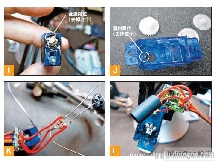
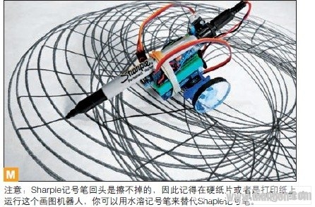
Any servo motor can be changed to a two-way variable speed motor. Generally speaking, controlling the speed and direction of the motor requires a motor drive chip and other components, and these components are already available on the servo motor. The modified servo motor is the most common and cheapest, and the method of digitally controlling the transmission used in the robot is obtained, so that a servo motor that continuously rotates is obtained. This change is partly mechanical and partly electrical. The electrical modification part is to change the potentiometer into two fixed resistors with the same resistance value. The mechanical modification part is to remove the limit device that prevents the motor from rotating in all directions. First disassemble the servo motor. The HTX500 servo motor housing is made up of three plastic clips that can be opened with a small slotted screwdriver or similar sheet. Pull the gear away from the top and carefully pull the servo motor control board out from underneath (see Figure I). There are two mechanical limit positions inside. The bending of the needle-nosed pliers can remove the metal limit beside the rotating shaft. The diagonal cutter can remove the plastic limit on the top shell (see Figure J). Replace the 5kΩ potentiometer with two fixed resistors that add up to about 5kΩ, and two 2.2kΩ resistors. De-solder the three wires on the potentiometer and solder the two resistors as shown in Figure K. Wrap the new assembly with insulating tape or heat-shrink tubing (see Figure L), then plug the circuits back into the servo motor housing and install the housing. The modification is complete, now you can calibrate this continuously rotating servo motor to see where the starting point is. If the resistance values ​​of the two resistors are exactly equal, the motor can stop when it is sent to the servo motor at a 90° angle. Your motor may have a slight deviation. Try experimenting with the previous program to see which angle can stop the motor. Remember this value because each servo motor is different. Two continuous rotation servo motors complete a drawing robot With two continuously rotating servo motors we can complete a drawing robot. It uses two servo motors, a 9V battery, a small breadboard, an Adafruit Boarduino control board (clone version of the Arduino board), a Sharpie marker and several plastic turntables. This circuit is the same as the panoramic camera, and all the components are glued together with hot melt adhesive. Any turntable with a diameter of 2 to 7 cm can be used as a wheel, such as a plastic screw top cover. To enhance gravity, you can also wrap the edges of the wheel with tape. The setting of the servo motor is the same as before. The code should use the variable of the starting position of the motor just obtained from the experiment (the starting position of your motor may be different). The logic of the code moves one motor in one direction for a while and then switches to another motor. Now that you're done, you can try your robot (see Figure M). Installation Accessory,Encoder Sensor With Coupling,Encoder Sensor Wheel,Sensor Encoder Yuheng Optics Co., Ltd.(Changchun) , https://www.yuhengcoder.com