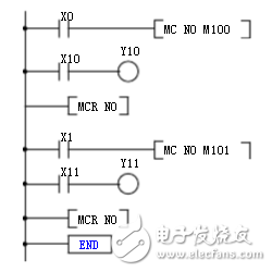
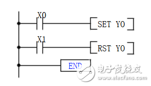
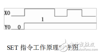
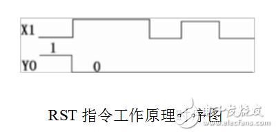
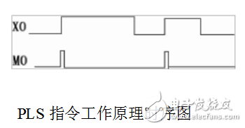
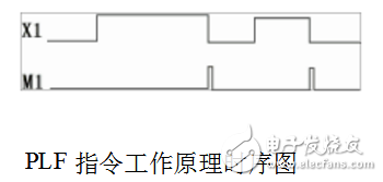
The timing diagram is a time-order diagram that describes the working process of the device and is a graph for visually analyzing the working process of the device. For example, triggers, timers, counters, etc. in electronic technology use timing diagrams to describe their working principle. In the plc sequential control design method, the ladder program is often drawn first, then the flow chart is designed according to the timing diagram, and then the ladder program is programmed according to the flow chart. Let's take a look at what the plc timing diagram looks like, and what is the use of related instructions. The instructions of the timing diagram are roughly divided into set and reset instructions, pulse output instructions, and master control commands and master reset commands . 1, the instruction symbol: Set instruction instruction: SET: Reset instruction: RST: 2, ladder symbol: The set and reset instructions are a set of function instructions. Use brackets or squares when drawing ladders, and connect the busbars after at least one contact. As shown below: 3. Command function: Function of the SET instruction: When the precondition of the SET instruction is working, X0 is positively changed (ie, X0 is turned from OFF to ON), the SET instruction sets the relay Y0 it operates to "1" (the state becomes ON) and remains . Function of the RST instruction: When the precondition of the RST instruction is X1, the positive transition (ie, X0 is turned from ON to OFF), the RST instruction resets the relay Y0 it operates to "0" (the state becomes OFF) and holds. The operation target elements of the SET instruction are Y, M, and S. The operating elements of the RST instruction are Y, M, S, D, V, Z, T, and C. For the same programming component, such as Y0 in the example, the SET and RST instructions can be used multiple times, and the order of use is not limited, and the last executor is valid. The RST instruction can clear the contents of the timer, counter, data register, and index register. It can also be used to reset the integrated timers T246 to T255 and the counter. 1, the instruction symbol: Rising edge pulse output command instruction: PLS; falling edge pulse output command command: PLF 2, ladder symbol: The pulse output command is a set of function instructions. When drawing a ladder diagram, use brackets or squares, and at least one contact can be used to connect the bus. As shown below: 3. Command function: The function of the PLS instruction is: When X0 has a positive transition, the PLS instruction causes the specified relay M0 to generate a pulse output of one scan period. The function of the PLF instruction is: When a negative transition occurs in X1, the PLF instruction causes the specified relay M1 to generate a pulse output of one scan period. The target components of the PLS and PLF instructions are Y and M, but special auxiliary relays cannot be used as target components. 1, the instruction symbol: Master start instruction instruction: MC: Master reset instruction command: MCR: The master and master reset commands are a set of function instructions. When drawing a ladder diagram, use brackets or squares, and at least one contact can be used to connect the bus. As shown below: 3. Command function: The function of the MC instruction is: When X0 remains ON, the program between the MC instruction and the MCR instruction is executed. When X0 is kept OFF, the program between the MC instruction and the MCR instruction is not executed. At this time, the non-integrated timer and the component driven by the OUT instruction are reset, and the timer, counter, and component driven by the SET/RST instruction are integrated. Keep the current state. In the above ladder diagram, when X0 remains ON and X1 remains OFF, press button X10, Y10 works and press button X11, Y11 does not work. The function of the MCR instruction is to cancel the master command. The target components of the MC and MCR instructions are Y and M, but special auxiliary relays cannot be used as target components. 4. Nesting of MC instructions: The MC instruction is called nesting in the MC command area, and the number (0 to 7) of the nesting level N is sequentially increased. When returning, the MCR instruction is used to cancel from the large nesting level. When programming with MC and MCR instructions, it is best not to use nesting to avoid errors. Car Phone Holder,Mobile Holder For Cars,Mobile Phone Holder For Dashboard,Mobile Phone Holder For Car Dashboard Ningbo Luke Automotive Supplies Ltd. , https://www.nbluke.com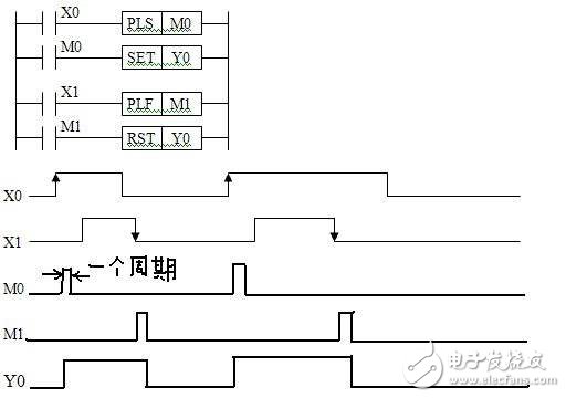
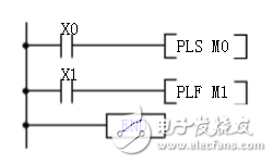
   2, ladder symbol: