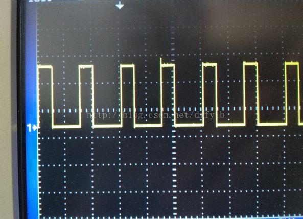
51 microcontroller can output PWM, more trouble. At this point you need to use an internal timer to achieve, you can use two timers to achieve, you can also use a timer to achieve. The method of using two timers is to use the timer T0 to control the frequency, and the timer T1 to control the duty ratio. The general programming idea is this: The T0 timer interrupt allows an I0 port to output a high level, starting timer T1 in the timer T0 interrupt, and this T1 is to let the IO port output low, so change the timing The initial value of T0 can change the frequency. Changing the initial value of timer T1 can change the duty cycle. The following focuses on using a timer to implement the PWM method. Taking a period of 1ms (1kHZ) as an example, to generate PWM waves of other frequencies, a simple modification is required in the program. When using a timer (such as timer T0), first determine the PWM cycle T and duty cycle D, after determining these, you can use a timer to generate a time reference t, such as the timer overflow n times is The high PWM time, then D*T=n*t, can similarly determine how many time references n are required for the PWM low time. Because here we are generating a PWM with a period of 1ms (1kHZ), we can set the time base of the interrupt to be 0.01ms, and then interrupt it 100 times for 1ms. Within the interrupt subroutine, you can set a variable such as time. Within the interrupt subroutine, there are three important statements: 1, when time> = 100, time clear (this statement to ensure the frequency of 1kHZ); 2, when time> n (n should be changed between 0-100), so that a single-chip corresponding I / O port output low; 3. When time<=n, let the corresponding I/O port of a single chip output high, and the duty cycle is %n. The following program generates a 30% duty cycle pwm: #include #define uint unsigned int #define uchar unsigned char Sbit PWM=P2^0; // P2.0 output pwm Uchar time; // define the duty cycle variable Void main() { TMOD=0x01;// Timer 0 operation mode 1 TH0=0xff;//(65536-10)/256; //Initial timing TL0=0xf7;//(65536-10)%256;//0.01ms EA=1;//Open total interrupt ET0=1;//Open timer 0 interrupt TR0=1;//Start timer 0 While(1) { } } Void tim0() interrupt 1 { TR0=0; // When the initial value is assigned, turn off the timer TH0=0xff;//(65536-10)/256; //Initial timing TL0=0xf7;//(65536-10)%256;//0.01ms TR0=1;//Open timer Time++; If(time>=100) Time=0; If(time<=30) PWM=1; Else PWM=0; } The final waveform is shown on the oscilloscope as shown below: If you want to modify the duty cycle, modify the following sentence directly in the program. If (time <= 30) / / duty cycle% 30, can change the duty cycle Ms001 3000Puffs Vape,Mini Electronic Cigarette,Vape Electric Cigarette,Electronic Cigarette Vape Puff Bar Guangzhou Yunge Tianhong Electronic Technology Co., Ltd , https://www.e-cigarettesfactory.com