Introduction to DC Power Supply DC power has two electrodes, positive and negative. The potential of the positive pole is high and the potential of the negative pole is low. When the two electrodes are connected to the circuit, a constant potential difference can be maintained between the two ends of the circuit. A current from the positive electrode to the negative electrode is formed in the external circuit. The difference between the water level and the height cannot maintain a steady flow of water, and by continuously pumping water from a low place to a high place, a certain water level difference can be maintained to form a steady water flow. Similarly, the electrostatic field generated by the charge alone cannot maintain a constant current, and with the help of the DC power source, the non-electrostatic effect (referred to as "non-electrostatic force") can be used to make the positive charge from the negative electrode with a lower potential. Returning to the positive electrode with higher potential through the internal power supply to maintain the potential difference between the two electrodes, thereby forming a constant current. Therefore, a DC power source is an energy conversion device that converts other forms of energy into a power supply circuit to maintain a constant current flow. The DC system is mainly composed of two major parts. Part of the battery screen is a DC charging screen (DC screen). The battery screen is a cabinet (800 & TImes; 600 & TImes; 2260) that can hold multiple batteries. The battery in the battery screen is generally composed of a 2V-12V battery in a series of 9 to 108 series, and the corresponding voltage output is 110V or 220V. The batteries currently in use are mainly valve-regulated sealed maintenance-free lead-acid batteries. The DC screen is mainly composed of cabinet, rectifier module system, monitoring system, insulation monitoring unit, battery inspection unit, switch quantity detection unit, step-down unit and a series of power distribution units such as AC input, DC output, voltage display and current display. . Card Holder Connector,Push Card Smt Card Holder Connector,Smt 8P Card Holder Connector,Smt Card 8P Card Holder Connector Dongguan Yangyue Metal Technology Co., Ltd , https://www.yyconnector.com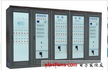
1. Rectifier module system: The power rectifier module is a single-machine module that rectifies AC power into DC power, usually rated by current magnitude (such as 2A module, 5A module, 10A module, 20A module, etc.), according to different design concepts. Can also be divided into: air cooling module, independent air duct module, self cooling module, self-energy air cooling module and self-cooling module. It can be used in parallel in multiple units to achieve N1 redundancy. The module output is a stable and adjustable DC voltage of 110V and 220V. The module itself has various perfect protection functions such as input overvoltage protection, output overvoltage protection, output current limiting protection and output short circuit protection.
2. Monitoring system: The monitoring system is the core of control and management of the entire DC system. Its main tasks are: long-term automatic monitoring of each functional unit and battery in the system, obtaining various operating parameters and states in the system, according to the measured data and The operating state is processed in time, and the system is controlled based on this, realizing the automatic management of the power system to ensure the continuity, reliability and safety of its work. There are two types of monitoring systems: one is a button type and the other is a touch screen type. : The monitoring system provides man-machine interface* to realize system operation parameter display, system control operation and system parameter setting.
3. Insulation monitoring unit: The DC system insulation monitoring unit is a device for monitoring the insulation of the DC system. It can monitor the line-to-ground leakage resistance in real time. This value can be set according to the specific conditions. When the line-to-ground insulation is reduced to the set value, an alarm signal is issued. The DC system insulation monitoring unit currently has bus insulation monitoring and branch insulation monitoring.
4. Battery inspection unit: The battery inspection unit is a device for detecting the on-line voltage of the battery. It can detect the voltage of each battery in real time. When the battery voltage is higher or lower than the setting, an alarm signal will be sent and the monitoring system will show which battery has failed. The battery inspection unit can generally detect 2V-12V battery and patrol ring detection 1-108 batteries.
5. Switch quantity detection unit: The switch quantity detection unit is a kind of equipment for on-line detection of switch quantity and output of alarm dry node. For example, in the whole system, which circuit breaker has a fault trip or which fuse is blown, the switch quantity detecting unit will send an alarm signal, and the monitoring system can show which circuit breaker has a fault trip or which way is blown. The fuse is blown. At present, the switch quantity detecting unit can collect 1-108 way switch quantity and multiple passive dry node alarm output.
6. Buck unit: The step-down unit is a step-down regulator device. It is a combined voltage input step-down unit. The step-down unit is output to the control unit, and the control master voltage is within the set range (110V or 220V). When the combined voltage changes, the buck unit automatically adjusts to ensure that the output voltage is stable. The buck unit is also nominally the magnitude of the output current. There are currently two types of step-down units, one is a step-down silicon chain, and the other is a stepless step-down chopper. The step-down silicon chain has 5 steps and 7 steps, and the voltage regulation point is 3.5V, which means that the step-down silicon chain automatically adjusts the stable control voltage when the voltage is increased or decreased by 3.5V. Stepless step-down chopper is a step-down module. It is smaller than the step-down silicon chain. It has no voltage regulation point, so the output voltage is also stabler than the step-down silicon chain. There are overvoltage, overcurrent, and battery overdischarge. And other functions. However, the current stepless step-down chopper technology is not very mature and often fails, so the buck silicon chain is widely used.
7. Power distribution unit: The power distribution unit is mainly used in the DC screen for the functions of AC input, DC output, voltage display, current display, etc., such as: power line, terminal block, AC circuit breaker, DC circuit breaker, contact. , lightning arresters, shunts, fuses, transfer switches, push button switches, indicator lights, and current and voltage meters.
Basic working principle and analysis of DC power supply When the mains converts the mains voltage into the designed voltage through the input switch to the transformer, it enters the pre-regulator circuit, which pre-regulates the required output voltage. The purpose is to reduce the tube voltage drop between the input and output of the high power adjustment tube, reduce the power consumption of the high power adjustment tube, and improve the working efficiency of the DC power supply. The pre-regulated power supply is generally adjusted by the stepless phase shift of the thyristor. The relay is switched by the relay to switch the output of the transformer. After the pre-regulated power supply and the filter 1, the voltage obtained by the relatively stable ripple is relatively small. After the accurate and rapid pressure is applied to the high-power adjustment tube controlled by the control circuit, the voltage regulation accuracy and performance are met. The DC voltage is filtered by filter 2 to get my desired output DC. In order to get my desired output voltage value or steady current value, we also need to sample the output voltage and current values. And transmitting it to the control/protection circuit, the control/protection circuit compares the detected output voltage value and current value with the value set by the voltage/current setting circuit, and drives the pre-regulator circuit and the high-power adjustment tube. The DC stabilized power supply can output the voltage and current values ​​we set, and when the control/protection circuit detects an abnormal voltage or current value, the protection circuit will be activated to make the DC power supply enter the protection state.