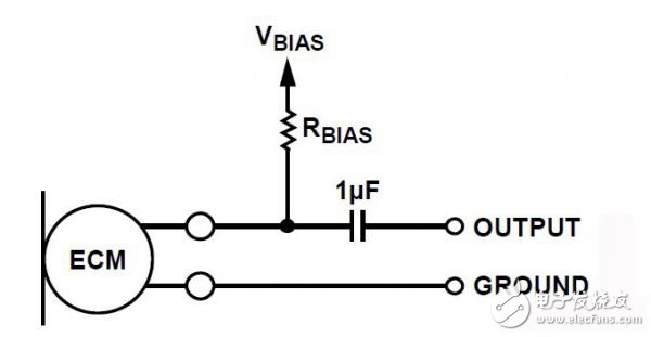
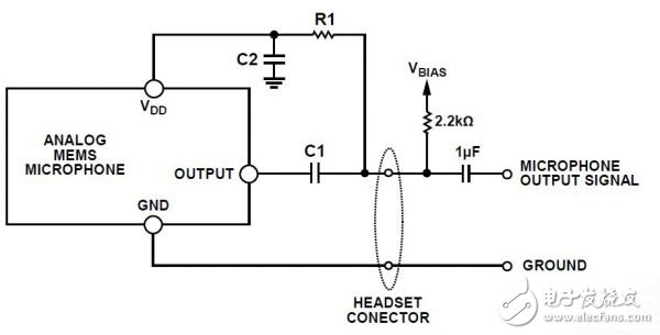
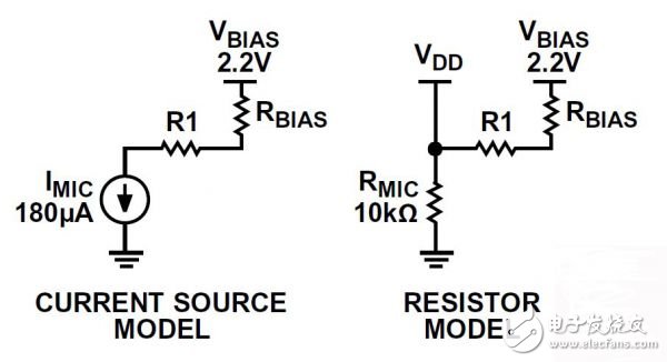
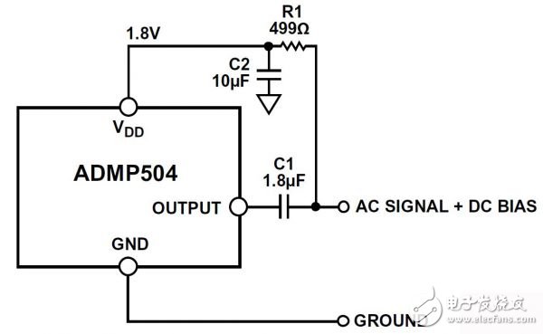
Today MEMS microphones are gradually replacing electret condenser microphones (ECM) in audio circuits. The functions of the two microphones, ECM and MEMS, are the same, but the connections between each and the rest of the system are different. This application note will introduce these differences and provide design details based on a simple replacement circuit based on a MEMS microphone. ECM has two signal leads: output and ground. The microphone is biased by DC bias on the output pin. This bias is usually provided through a bias resistor, and the signal between the microphone output and the preamplifier input is AC coupled. A common use case for ECM is to use as an inline voice microphone in a headset connected to a mobile phone. In this case, the connector between the headset and the phone has four pins: left audio output, right audio output, microphone signal, and ground. In this design, the output signal of the ECM and the DC bias voltage are transmitted in the same signal line. The bias voltage source is usually about 2.2 V. No input bias voltage is used on the signal pins of the analog MEMS microphone. However, it is a three-terminal device with different pins for power, ground, and output. The supply voltage of the VDD pin is generally 1.8 to 3.3 V. The signal output of the MEMS microphone is biased by a DC voltage, which is generally equal to or close to 0.8 V. In the design, the output signal is usually AC coupled. Figure 1. ECM circuit connection Compared with ECM, the key advantage of using MEMS microphone is its stronger power supply rejection (PSR) performance. The PSR of a MEMS microphone is usually at least 70 dBV, but ECM has no power supply rejection capability at all, because the bias voltage is directly connected to the microphone through a resistor. Circuit changes required to replace ECM with MEMS microphones For a system originally designed around ECM, the basic problem when switching to a MEMS microphone is that there is no separate signal for the power supply and the microphone output, such as when using a headphone microphone. If you make some small changes to the circuit, you can use MEMS microphones in this type of design. First, the downstream signal provided by the DC bias in the signal chain must be isolated from the output signal of the microphone. Secondly, this DC bias must be used to power the MEMS microphone, and the output signal of the microphone must not interfere with the power supply. Isolation of the DC bias can be achieved by AC coupling capacitors, and the power supply for the MEMS microphone can be provided by a carefully designed circuit that acts as a voltage divider and low-pass filter. The following design uses the ADMP504 MEMS microphone as an example. A 2.2 k bias resistor is used. Figure 2. A MEMS microphone using one wire for power and output signal Figure 2 shows a design example that implements the above functions. In the design of the headset, the circuit part on the left side of the headset connector will be in the actual headset, and the 2.2 k bias resistor and 1 F AC coupling capacitor will be in the source device (such as a smart phone). Resistor R1 and R bias form a voltage divider, and the MEMS microphone reduces the V bias voltage to the supply voltage of the VDD pin. Depending on the value of V bias, R bias and the required VDD voltage, resistor R1 may need to be very small, as shown in the following example. To calculate the required series resistance (R bias + R1), the microphone can be modeled as a resistor, through which a fixed current will flow. When VDD = 1.8 V, the typical supply current of the ADMP504 is 180 A. According to Ohm's law, when the voltage on VDD is 1.8 V, the microphone can be modeled as a 10 k resistor. It is required to solve the appropriate resistance R1 value, the voltage divider formula used is: [Microphone VDD] = [bias voltage] &TImes; (10 k / (10 k + R1 + R bias According to this formula, it can be calculated that a 2.2 k R bias resistor and a 499 R1 resistor will divide 1.73 V from the 2.2 V bias voltage to the microphone's VDD. When choosing the value of R1, trade-offs need to be made; as shown below, if this value is too large, VDD will be too small, but in order to prevent C2 from being too large, this value cannot be made too small. Today MEMS microphones are gradually replacing electret condenser microphones (ECM) in audio circuits. The functions of the two microphones, ECM and MEMS, are the same, but the connections between each and the rest of the system are different. This application note will introduce these differences and provide design details based on a simple replacement circuit based on a MEMS microphone. Figure 3. Voltage divider model Figure 3 shows two different models of the voltage divider. On the left, the ADMP504 microphone is modeled as a 180 A current source; on the right, the microphone is modeled as a 10 k resistor with 1.8 V VDD. The capacitor C2 and the resistor R1 form a low-pass filter, which is used to filter the microphone audio output in the voltage supply signal. The corner frequency of this filter should be much lower than the lower corner frequency of the microphone itself. Designing the low-pass filter to be at least two octaves below the lower corner frequency of the microphone is a good start. For ADMP504, this corner frequency is 100 Hz. A capacitor of 10 F and a resistor of R1 of 499 can realize a filter with a corner frequency of 31 Hz. Larger capacitors or resistors will further reduce this corner frequency, but the size of the filter's resistance must be balanced with its contribution to the voltage divider, which provides VDD to the microphone. The calculation formula for the −3 dB point of the low-pass filter is as follows: f−3 dB = 1/(2π &TImes; R1 &TImes; C2) among them: R1 is the resistance in the voltage divider. C2 is the low-pass filter capacitor. Capacitor C1 AC-couples the microphone output so that its bias output is isolated from the microphone bias voltage provided by the mobile phone. Under the given VDD condition, by virtue of R bias, R1 and the equivalent resistance of the microphone, the capacitor will also form a high-pass filter. The total resistance to be considered when calculating the corner frequency of the high-pass filter is the series resistance of RMIC and R1 in parallel with R bias. The calculation formula for this resistance is Rtotal = ((RMIC + R1) &TImes; R bias)/(RMIC + R1 + R bias) For the example here, Rtotal = 1810. The corner frequency of the high-pass filter is: f−3 dB = 1/(2π(Rtotal × C1) To make the filter corner frequency at least one octave lower than the ADMP504 low-frequency roll-off frequency of 100 Hz, the filter corner frequency is 100 Hz, and C1 should be at least 1.8 F. Figure 4. Circuit using ADMP504 MEMS microphone Figure 4 shows a complete set of headphone circuit, which uses the ADMP504MEMS microphone and appropriate resistance and capacitance values, and based on the V bias and R bias values ​​we deal with. With the circuit introduced in this article, it is possible to use MEMS microphones in designs that do not have a separate power supply and microphone output signal. This circuit only uses two capacitors and one resistor, allowing MEMS microphones to be used in two-wire microphone circuits.
High temperature wire, high temperature resistant wire, please don't take the safety of electricity as a bet, but the quality and credibility of your own products as a bet. If you want to find a regular cable, and find a regular manufacturer, our cables are instantly conductive, stronger and safer than others, refreshing your imagination of materials. We will spend a lifetime of continuous improvement, just to achieve the real environmental protection level of materials and reduce carcinogens. Only for health, a truly environmentally friendly material. Safety check, every product has been tested. High-precision wires have lower resistance, lower heat, and lasting and stable conductivity. Real-time monitoring of wire eccentricity and outer diameter to ensure uniform thickness of insulation layer and sheath. Eliminate the addition of heavy metals and non-environmentally friendly substances such as lead, mercury and other harmful substances. Does not contain any harmful substances to avoid adverse effects on the human body and the environment.
We eliminate mold costs and save money for customers by providing hundreds of thousands of inventory overmolding. For highly customized molded cable manufacturing projects, our advanced technology allows us to produce custom overmoldings at a price and quality level that clearly sets us ahead of our competitors.
Custom molded wire assembly, overmolded IP67/68 connectors assembling,customized waterproofing cable assembly ETOP WIREHARNESS LIMITED , https://www.oemwireharness.com


