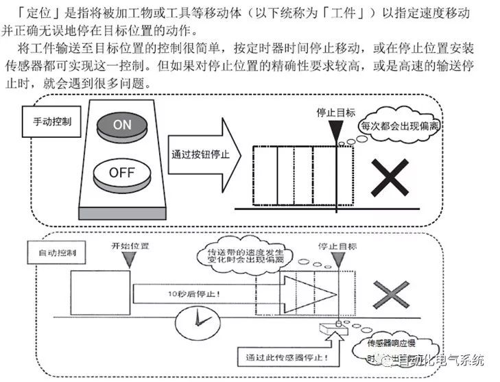
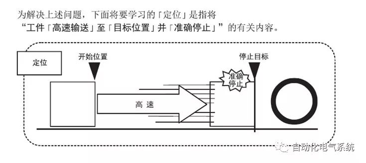
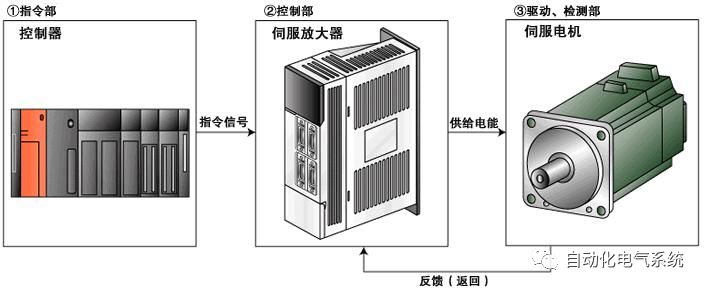
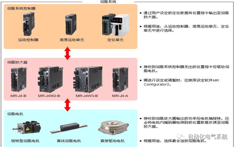
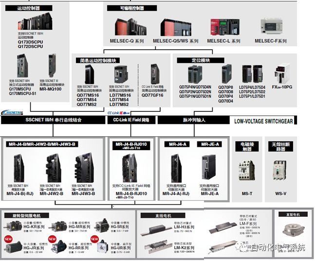
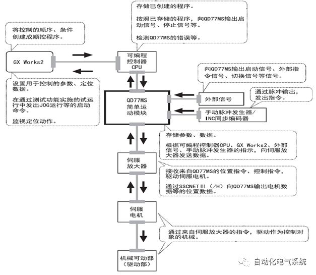
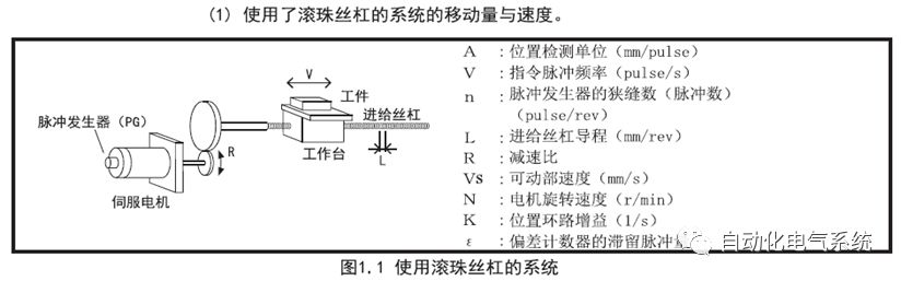
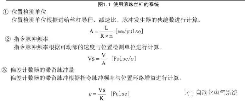
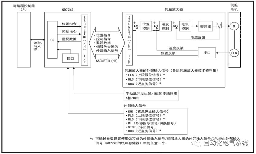
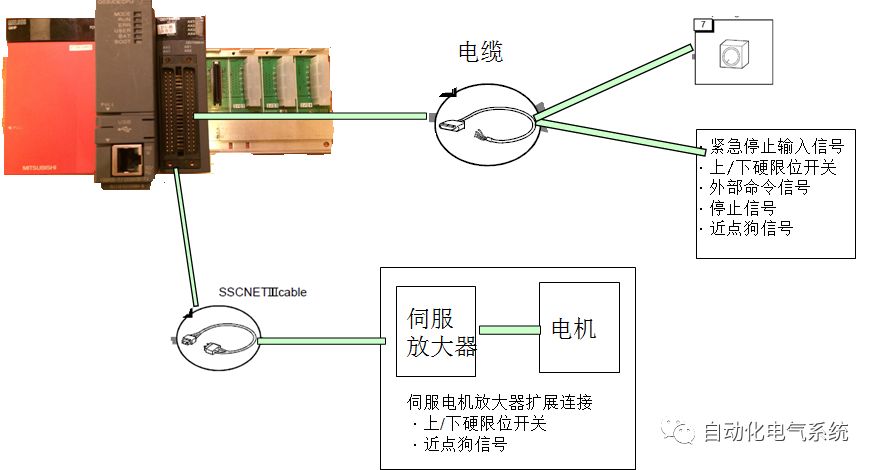
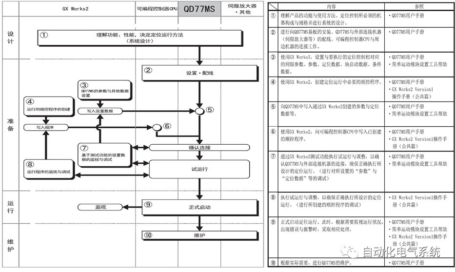
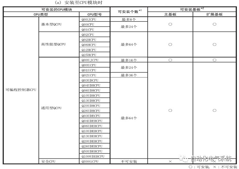
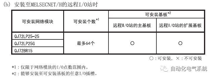
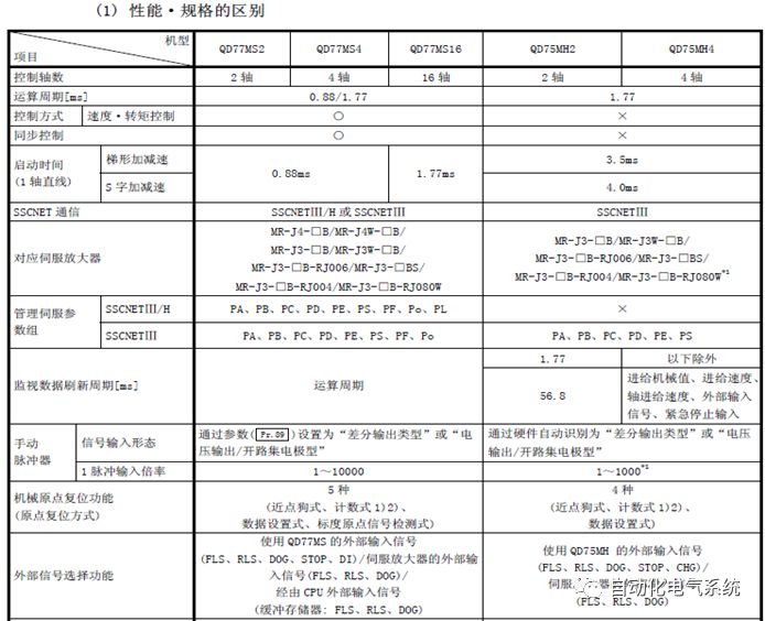
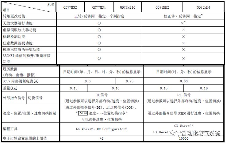
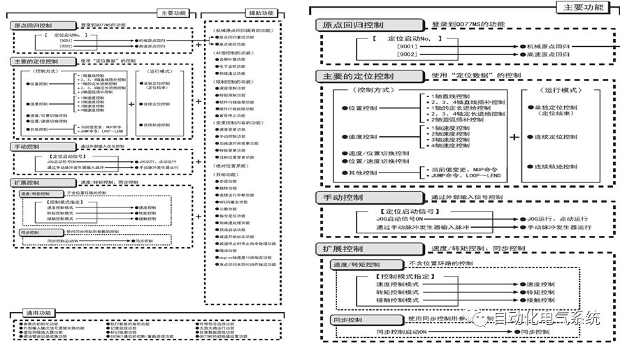
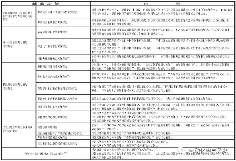
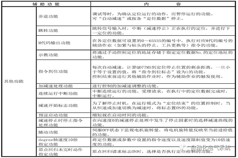
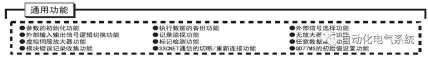
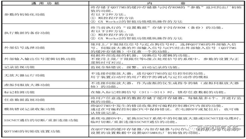
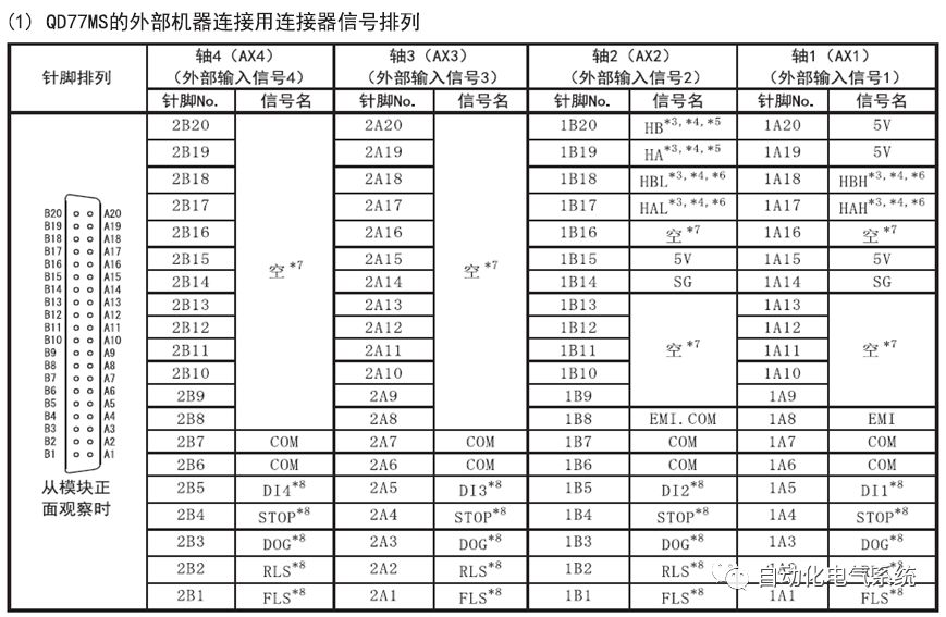
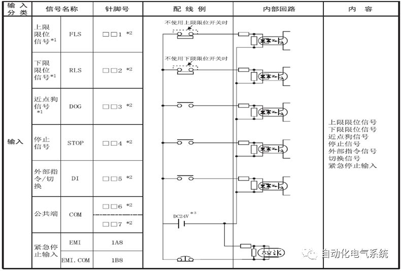
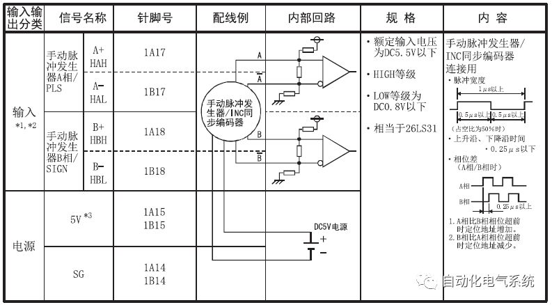
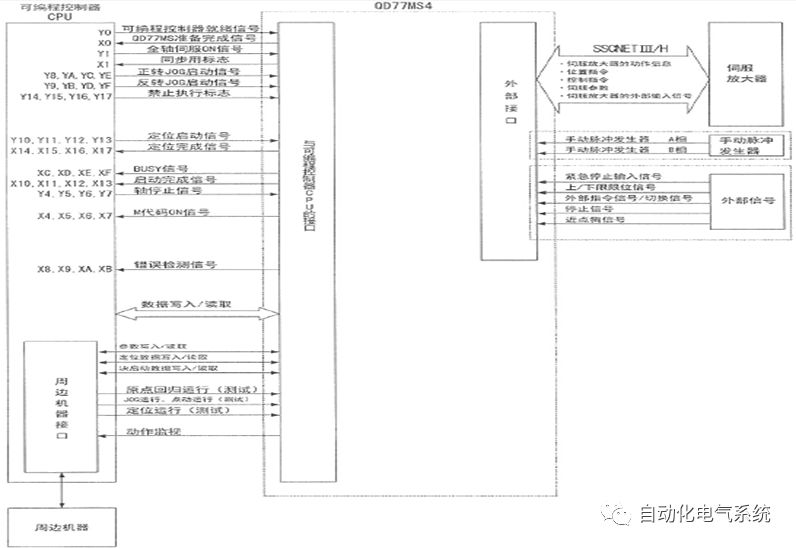
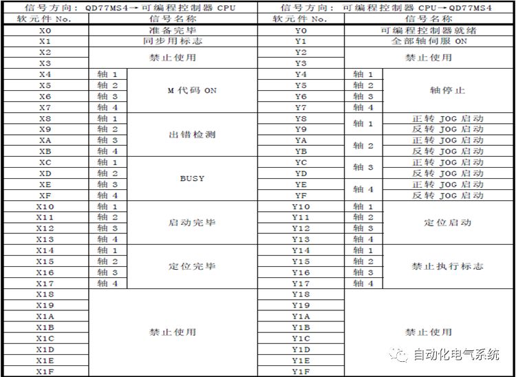
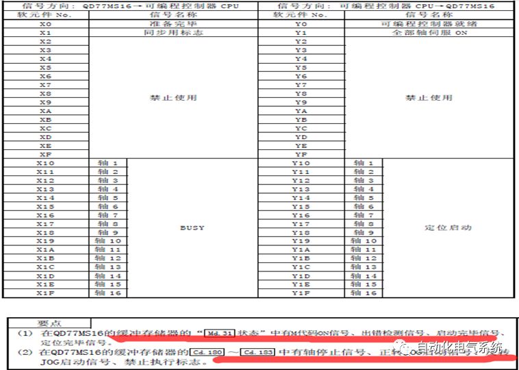
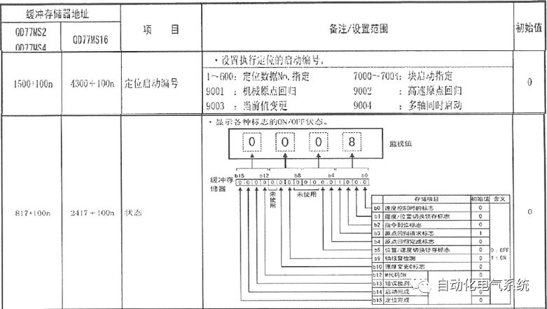
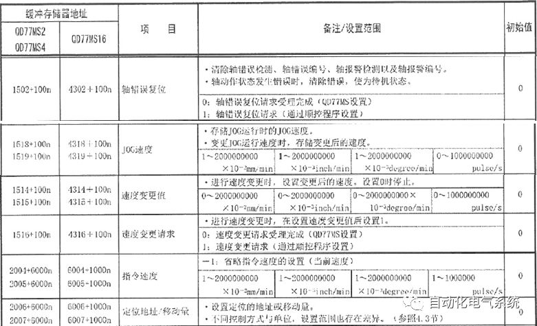
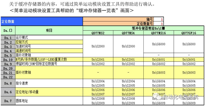
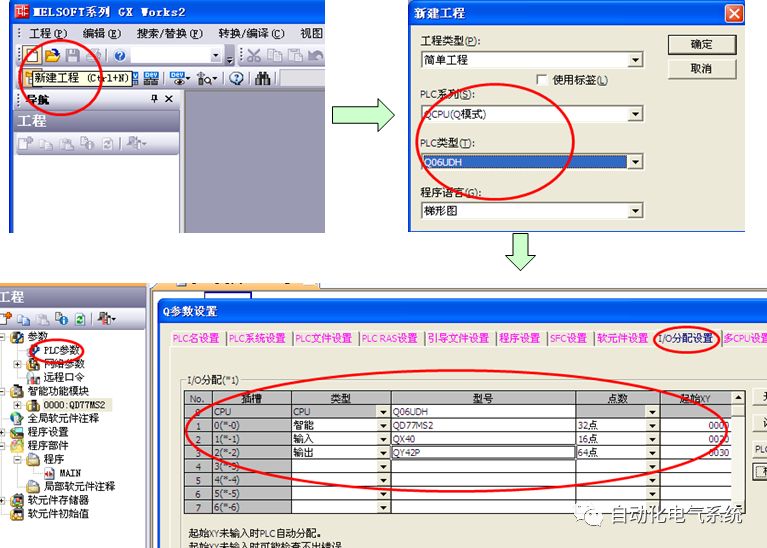
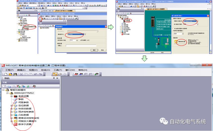
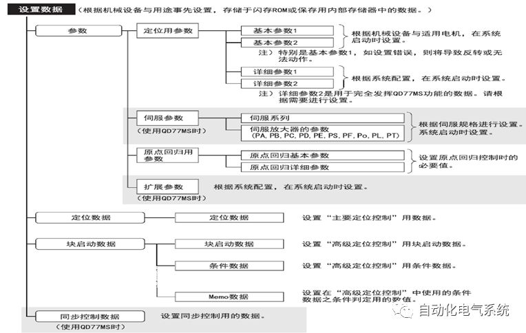
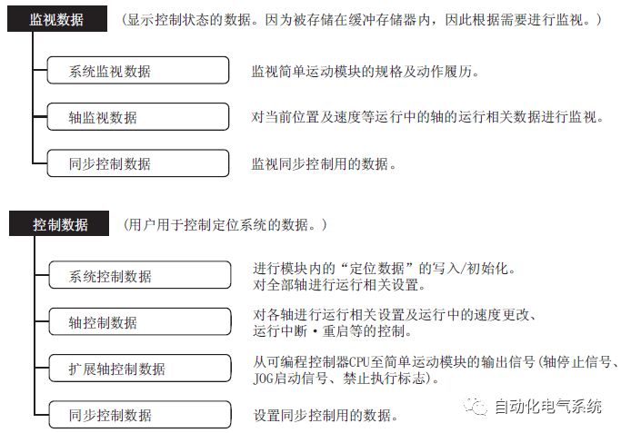
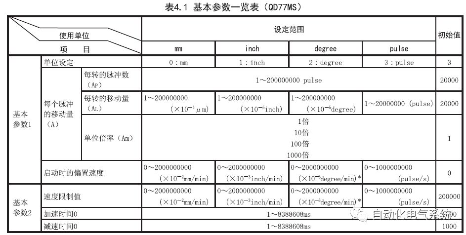
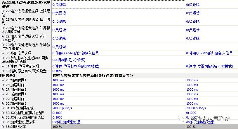
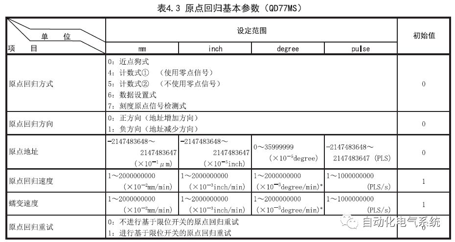
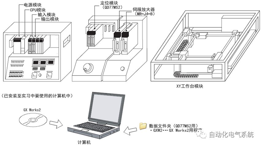
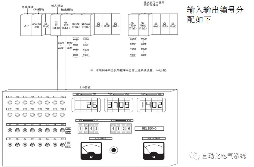
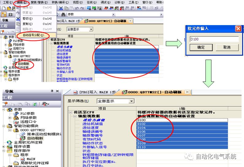
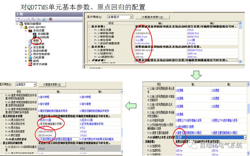
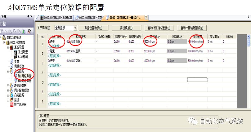
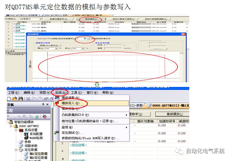
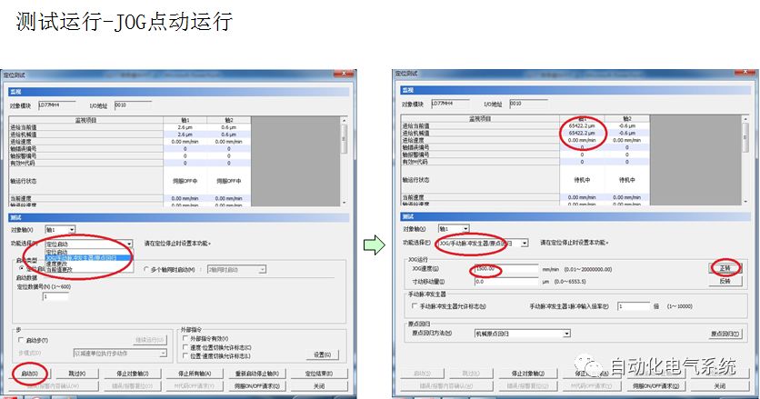
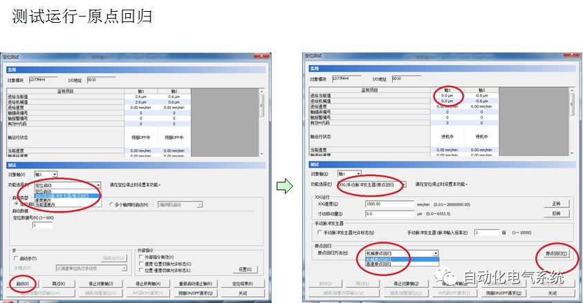
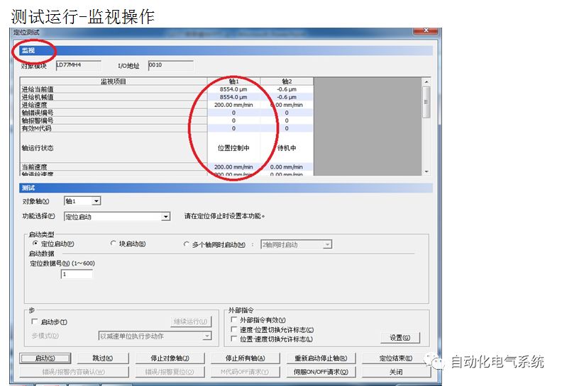
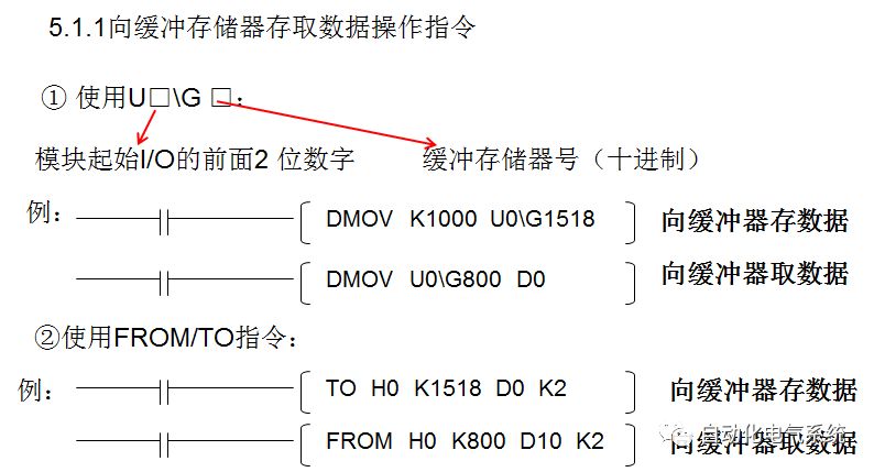
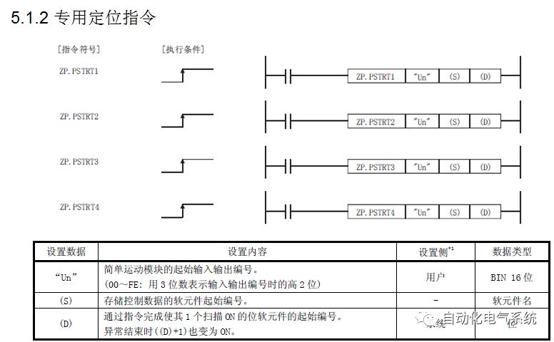
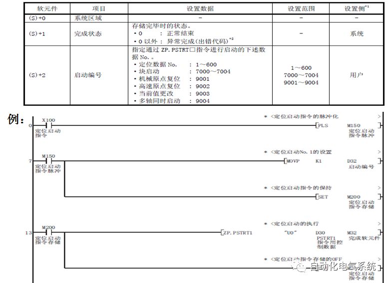
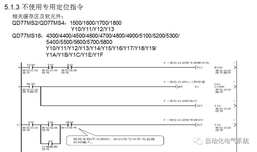
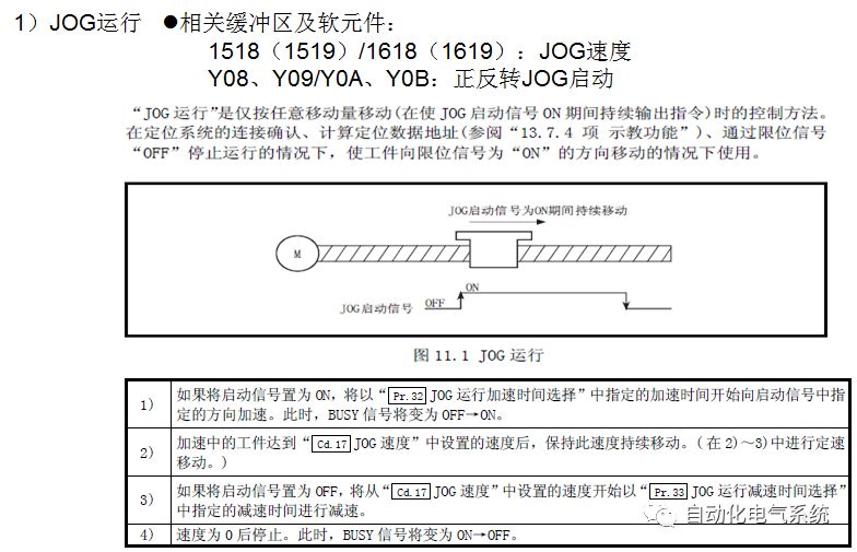
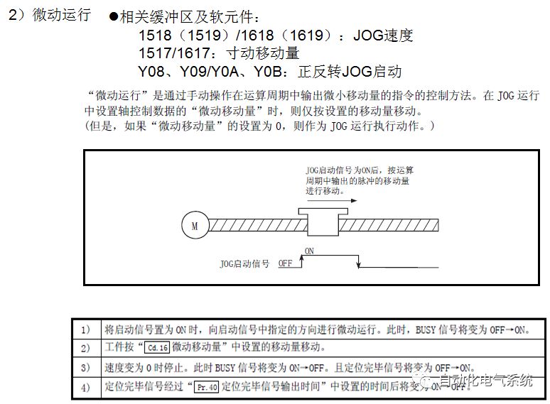
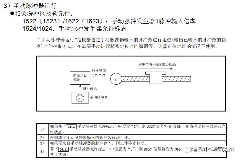
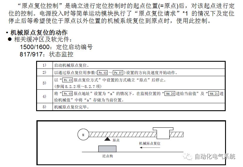
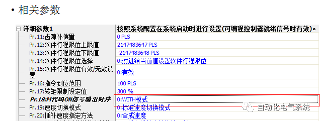
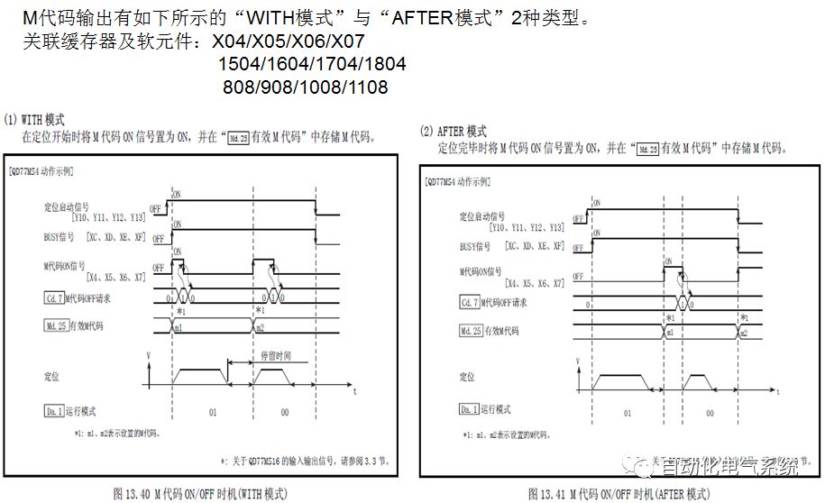
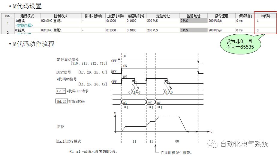
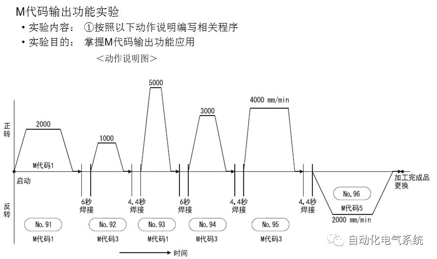
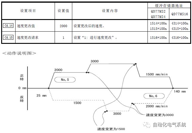
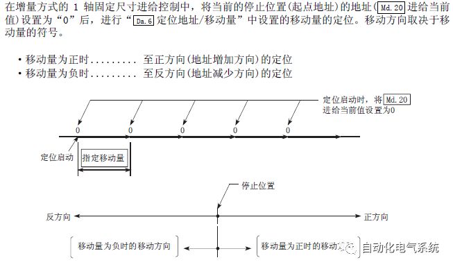
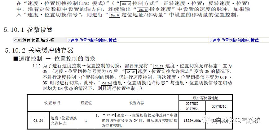
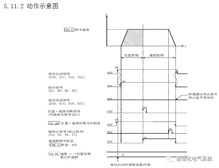
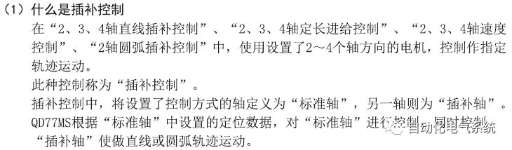
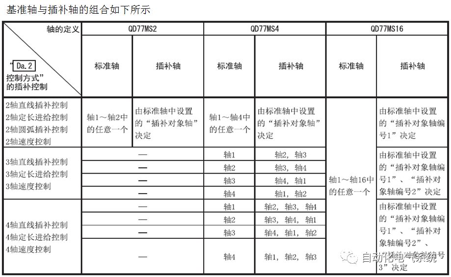
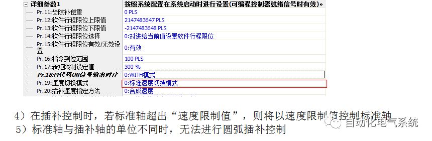
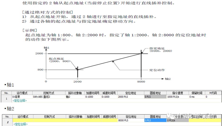
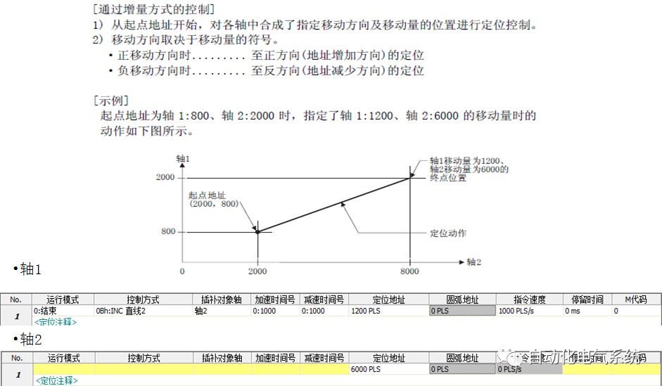
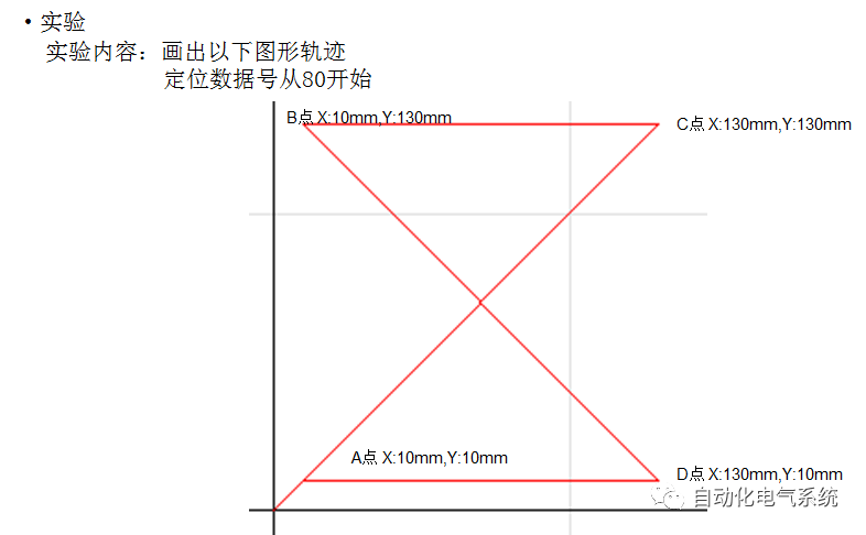
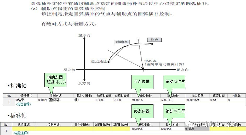
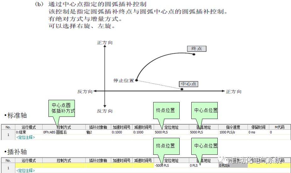
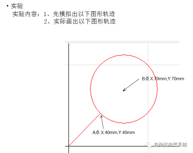
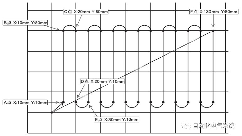
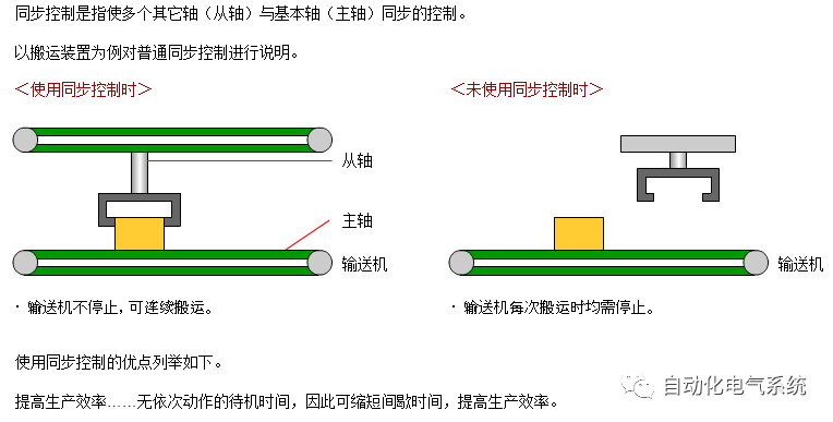
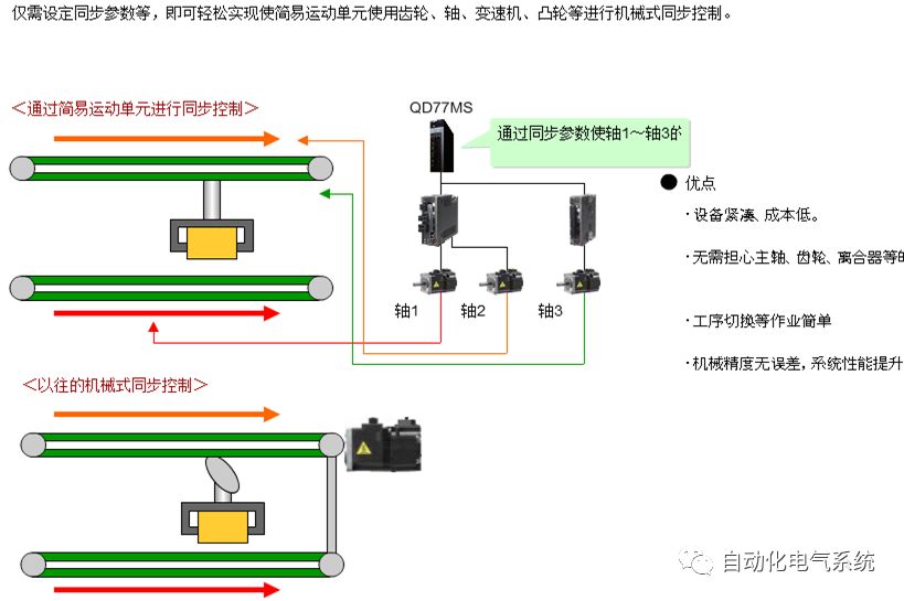
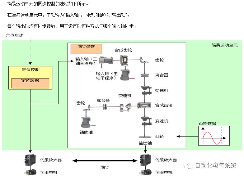
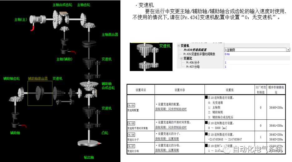
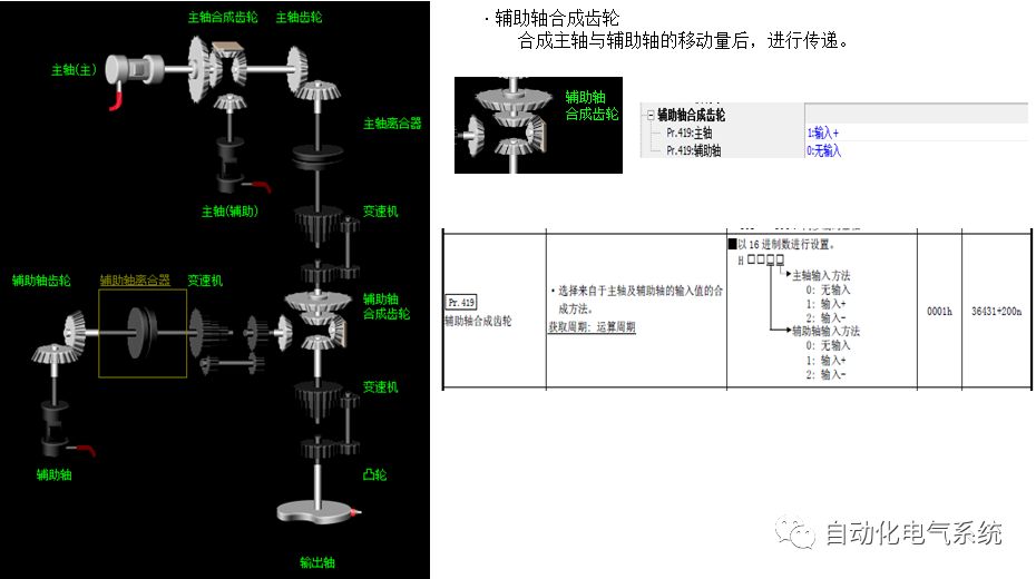
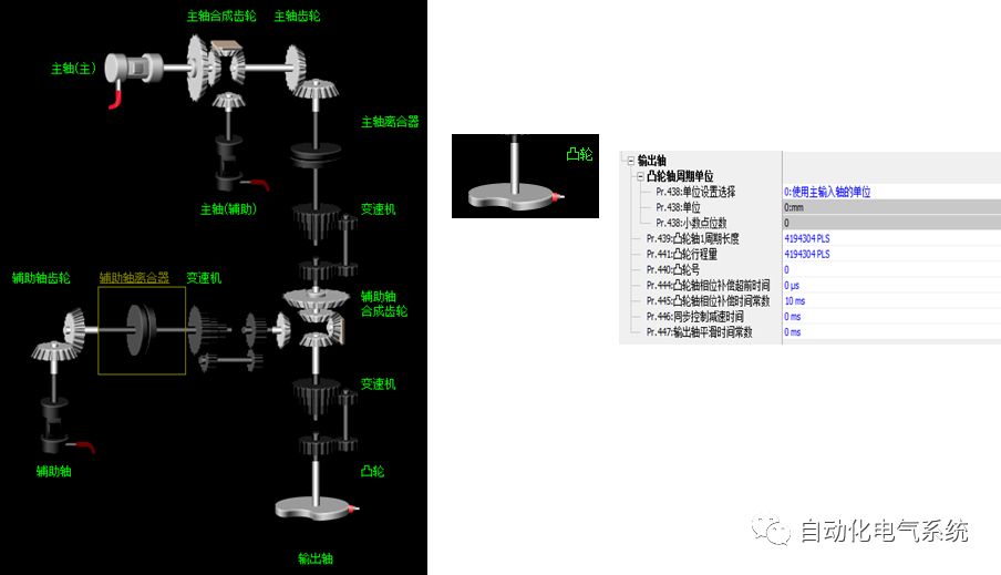
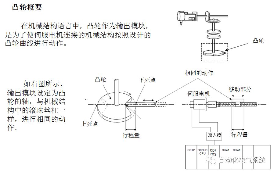
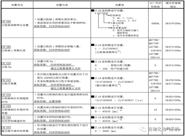
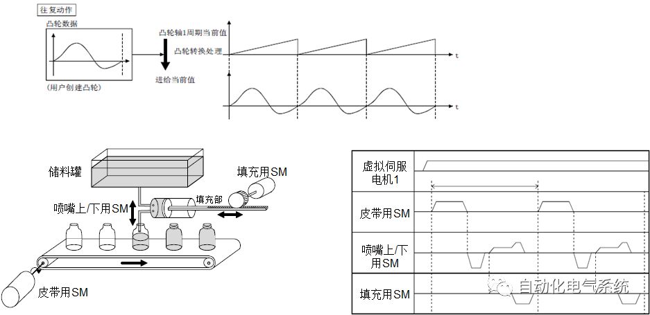
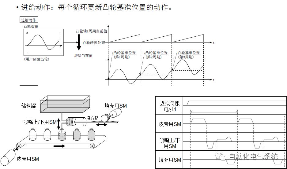
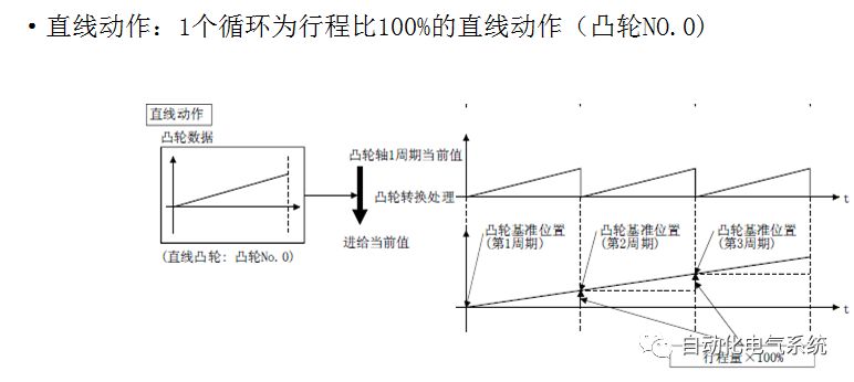
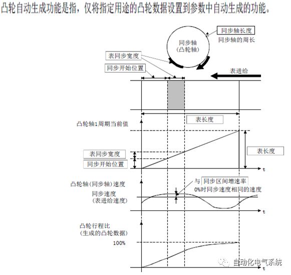
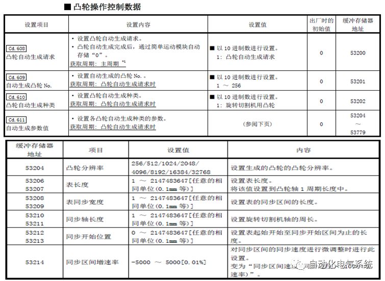
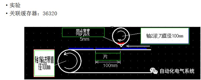
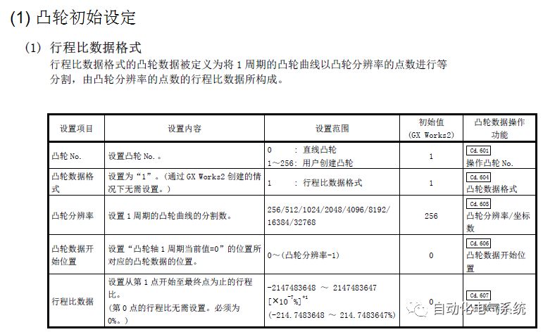
1. Purpose and purpose of positioning control 1.1 What is positioning control 1.2 The composition of the positioning system The precise positioning control system is also called the servo system. Servo system consists of servo system controller, servo amplifier and servo motor The servo amplifier is based on the user input in the controller the target value (position, speed, etc.), the position of the servo system controller to receive information on the current value (position, speed and other feedback signals) to detect, drive the servo motor is always towards the narrow Institutions that control the direction of the target value gap The positioning system formed by the simple motion unit is a smart unit that is controlled by a programmable controller CPU and can easily implement positioning control. QD77MS positioning control 1.3 General Design of Positioning Control The positioning system using QD77 simple motion unit is probably designed as follows QD77MS system overview 1.4 positioning system application process 1.5QD77MS system installation number 2. The specifications and functions of the simple motion module QD77 2.1QD77MS Performance Specifications The difference between 2.2QD77MS and QD75MH The functions of the QD77MS are divided into three parts: the main control function, the general function, and the auxiliary function. Reference materials 3-6. 2.3QD77MS Features 2.4 Interface with external input and output a) Interface with external input signal/emergency stop input signal b) Manual Pulse Generator/INC Synchronous Encoder 2.5QD77MS and PLC input and output signal specifications 2.6 commonly used buffer memory QD77MS has buffer memory, which can be read and written by the sequence program to achieve advanced control. The following describes the commonly used buffer memory. 3. Kind of data 3.1QD77MS Project Newly Built 3.2 Kind of data The parameters and data required when using the QD77MS control include "setting data", "monitoring data", "control data" 3.3QD77MS parameters 3.3.1 Basic parameters 3.3.2 Detailed parameters 3.3.3 Origin Return Parameters 3.4 Servo parameters 4. Implement the test run with GX Works2 4.1 System composition of internship equipment The training internship equipment consists of Q series PLC training equipment, QD77MS simple movement module, MR-J4-B servo amplifier and XY table 4.2 Automatic refresh settings 4.3 Performing a Test Run with GX Works2 5. Perform 1-axis positioning operation by sequence program 5.1 Operation Instructions 5.2 Manual Control “Manual control†is a control that performs arbitrary positioning operations based on input of signals from outside without using positioning data. "Manual control" includes three control methods: JOG operation, jog operation, and manual pulser operation. 5.3 Origin Control 5.4 Positioning Control 1) "Positioning control" is the control using "positioning data" stored in a simple motion module. 2) Position control, speed control, etc. are performed by setting up the positioning data after setting necessary items through this “positioning dataâ€. 3) The "main positioning control" control method is set in the setting item "Da.2 control method" of the positioning data. The control defined as "Main Positioning Control" is based on the "Da.2 Control Mode" setting as shown below. However, the speed control set in “Da.2 Control Method†is the speed control that includes the position loop in the servo amplifier instructions. When performing speed control without position loop, use "speed/torque control". Yellow: The interpolation axis side of the interpolation control cannot be set Red: Items that must be set, have not been set or have failed Gray: No setting required (setting is invalid) -: No setting required (setting invalid) 5.5 M code output function "M code output function" is used to perform auxiliary work corresponding to the M code number (stopping clamping or drilling, changing tools, etc.) The function of the instruction. In each axis, the M code uses the 0-65535 number, attached to the positioning data. 5.6 Suspension and Restart of Actions • Temporary stop: Stop the origin return control, positioning control, JOG operation, and the axis stop signal ON. Jog operation, manual pulser operation, speed and torque control. ·Restart command: When positioning is stopped on the way for some reason (When the axis operation status is "Stopped"), if Set "1" in Cd.6 to position again from the stop position to the end point of the stopped positioning data. 5.7 Speed ​​Change in Positioning Control "Speed ​​change function" is a function that changes the speed in control to the newly specified speed at any timing. The changed speed is directly set in the buffer memory and the command is changed according to the speed (Cd.15 Speed ​​change request) Or the speed of the external command signal changes. 5.8 Fixed Feed • In "1. Axis fixed length feed control ("Da.2 control method" = fixed length feed 1), the axis set using 1 motor Directional fixed-length feed control. 5.9 Speed ​​Control Used to perform endless operations in the same direction, such as control of conveyors, conveyors, etc. In "1-axis speed control" ("Da.2 control method" = forward speed 1, reverse speed 1), the "Da.8 command speed" is continuously output along the axis direction where the positioning data is set. The pulse of speed is controlled until a stop command is input. The 1-axis speed control includes two types of "forward rotation speed 1" that are activated in the forward direction and "reverse rotation speed 1" that is started in the reverse direction. 5.10 Speed/position switching mode 5.11 Position/Speed ​​Switching Mode 6. 2-axis positioning operation by sequence program 6.1 What is Interpolation Control ·Interpolation control considerations 1) When starting the interpolation control, start the standard axis without starting the interpolation axis 2) When the operation mode is specified as "continuous positioning control", "continuous track control" and interpolation control, interpolation control must be set in the control method of all positioning data. 3) The speed at the time of interpolation control can be specified as one of "Synthetic speed" or "Standard axis speed". 6.2 2-axis linear interpolation control 6.3 2-axis circular interpolation control 6.4 Comprehensive Application ·experiment Experiment content: Draw the following traces · Experiment purpose: 1) Master the block start 2) Comprehensively master linear and circular interpolation applications 7. Synchronous operation through the implementation of the sequence program 7.1 Synchronous Operation Definition 7.2 Introduction to Synchronous Control Modules 7.3 Cam Data Cam action Synchronized output shaft for cam action. There are three modes of reciprocating motion, feeding motion, and linear motion. ·Reciprocating action: Reciprocating action within a certain cam stroke range 7.4 Cam Automatic Generation Function 7.5 Self-built cam data • The cam data is divided into two kinds of stroke ratio data format and coordinate data format. 7.6 Linear Motion Cam Data small Customizable Wiring Harnesses,Custom Engine Wiring Harness,OEM Engine Wiring Harness,OEM Wiring Harness Dong guan Sum Wai Electronic Co,. Ltd. , https://www.sw-cables.com