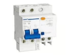
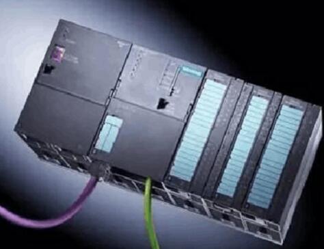
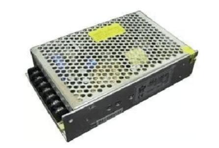
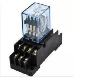
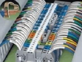
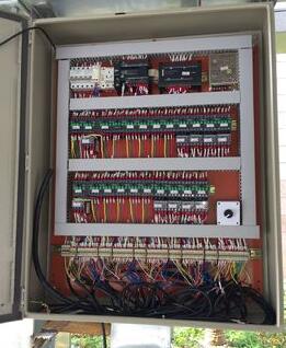
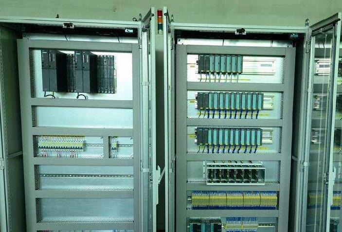
The PLC control cabinet refers to the programmable control cabinet, the control cabinet refers to the complete control cabinet, and the electrical cabinet that can control the motor and switch. The PLC control cabinet has protection functions such as overload, short circuit and phase loss protection. It has a compact structure, stable operation and complete functions. According to the size of the actual control regulations, the combination can be achieved. It can not only achieve single-cabinet automatic control, but also can realize multi-cabinet control system composed of industrial Ethernet or industrial field bus network (DCS). PLC control cabinet can adapt to various industrial automation and control applications. Widely used in electric power, metallurgy, chemical industry, papermaking, environmental protection, sewage treatment and other industries. 1, empty open A total air switch, which is the power control of the entire cabinet, is something that every cabinet must have. 2, PLC This should be selected according to the needs of the project. For example, if the project is small, it can be an integrated PLC. However, if the project is more likely to require modules and card-type, it may also need redundancy (that is, two sets of alternate use). 3, 24VDC power supply A 24VDC switching power supply, most PLCs are self-contained 24VDC power supply, according to whether it is really needed to determine whether the switching power supply. 4, relay General PLC can send instructions directly to the control circuit, but it may also be relayed by the relay first. For example, if the output of your PLC is charged at 24VDC, but the graph in your control loop that requires PLC is 220VAC, then you must add a relay to the PLC output. The relay operates, but then the control loop's node is connected to the normally open or normally closed point of the relay. It is also based on the situation whether to use the relay. 5, terminal blocks This is certainly something that is essential for every cabinet and can be configured based on the number of signals. If only a simple PLC control cabinet basically needs these things, if there are other things in your control cabinet, it depends on the situation. For example, you may have to supply power to certain on-site meters or a small control box, and you may have to increase the number of blanks. Or you need PLC to connect to the host computer, you may need to increase the switch or something. It depends on the situation. One, power The power of the programmable logic controller plays a very important role in the entire system. If a good, reliable power system is not working properly, manufacturers of programmable logic controllers also place great emphasis on the design and manufacture of power supplies. Normal AC voltage fluctuations are within +10% (+15%), and PLCs can be connected directly to the AC power network without taking other measures. Second, the central processing unit (CPU) The central processing unit (CPU) is the control hub of the programmable logic controller. It receives and stores the user program and data input from the programmer according to the functions given by the programmable logic controller system program; checks the status of the power supply, memory, I/O, and watchdog timer, and can diagnose syntax errors in the user program. When the programmable logic controller is put into operation, it firstly receives the status and data of each input device in the field by scanning, and stores them in the I/O mapping area respectively, and then reads the user program one by one from the user program memory. After the command is interpreted, the result of executing the logic or arithmetic operation according to the instruction is sent to the I/O image area or data register. After all the user programs have been executed, the output status of the I/O image area or the data in the output register is finally transmitted to the corresponding output device, and the cycle is repeated until it stops operating. In order to further improve the reliability of the programmable logic controller, in recent years, large-scale programmable logic controllers have also adopted dual CPUs to constitute a redundant system, or a three-CPU voting system. In this way, even if a CPU fails, the entire system can still operate normally. Third, the memory The storage system software memory is called system program memory. The memory for storing application software is called user program memory. Fourth, input and output interface circuit 1. The field input interface circuit consists of the optical coupling circuit and the input interface circuit of the microcomputer. The role is the input channel of the interface between the programmable logic controller and the field control. 2. The field output interface circuit is integrated by the output data register, the gating circuit and the interrupt request circuit, and the function programmable logic controller outputs the corresponding control signal to the execution part of the site through the field output interface circuit. Fifth, function module Such as counting, positioning and other functional modules. Sixth, communication module Working principle: When the programmable logic controller is put into operation, its working process is generally divided into three stages, namely input sampling, user program execution and output refresh. The completion of the above three phases is called a scan cycle. During the entire operation, the programmable logic controller's CPU repeatedly performs the above three phases at a certain scanning speed. 1, the input sampling stage In the input sampling phase, the programmable logic controller sequentially reads all input states and data in scan mode and stores them in the corresponding cells in the I/O map area. After the input sampling ends, it goes to the user program execution and output refresh phase. During these two phases, even if the input status and data change, the status and data of the corresponding unit in the I/O map area will not change. Therefore, if the input is a pulse signal, the width of the pulse signal must be greater than one scan cycle to ensure that the input can be read in any case. 2, the user program execution stage During the user program execution phase, the programmable logic controller always scans the user program (ladder) in the top-down order. When scanning each ladder diagram, it is always to scan the control circuit formed by each contact on the left side of the ladder diagram, and logically operate the control circuit formed by the contacts in the order of left, right, first, upper, and lower. Then, according to the result of the logic operation, the state of the corresponding bit in the system RAM memory area of ​​the logic coil is refreshed; or the status of the corresponding bit in the I/O image area is refreshed; or it is determined whether to execute the ladder diagram. Specified special function instructions. That is, during the execution of the user program, only the state and data of the input point in the I/O image area will not change, and other output points and software devices are in the I/O image area or system RAM memory area. Both the status and the data may be changed, and the ladder diagram above is listed. The result of the program execution will act on the ladder diagram below which all these coils or data are used. On the contrary, the ladder diagram below is The state or data of the logic coil being refreshed can only go to the next scan cycle to work on the program that is on top of it. If the immediate I/O instruction is used during program execution, the I/O point can be accessed directly. Even if the I/O instruction is used, the value of the input process image register will not be updated. The program will directly obtain the value from the I/O module and the output process image register will be updated immediately. This is somewhat different from the immediate input. 3, the output refresh phase When the user program is scanned, the programmable logic controller enters the output refresh phase. During this period, the CPU refreshes all of the output latch circuits according to the corresponding status and data in the I/O map area, and drives the corresponding peripherals through the output circuit. At this time, it is the true output of the programmable logic controller. Power supply: DC 24V DC, two-phase AC 220v, (-10%, +15%), 50Hz Protection class: IP41 or IP20 Environmental conditions: The ambient temperature is between 0°C and 55°C, to prevent direct sunlight; the relative humidity of the air should be less than 85% (no condensation). Keep away from strong vibration sources and prevent frequent or continuous vibrations with a vibration frequency of 10-55 Hz. Avoid corrosive and flammable gases. 1. The system structure is flexible, easy to expand, with switch control as its specialty; it can also perform PID loop control of continuous process; and it can form a complex control system with the host computer, such as DDC and DCS, to realize the integrated automation of the production process. . 2, easy to use, simple programming, the use of concise ladder diagrams, logic diagrams or statements and other programming languages, without the need for computer knowledge, so the system development cycle is short, on-site debugging is easy. In addition, the program can be modified online to change the control scheme without dismantling the hardware. 3, can adapt to a variety of harsh operating environment, anti-interference ability, strong reliability, much higher than other models. RAM/RFM Intermediate Frequency Capacitors RAM/RFM intermediate frequency capacitors Intermediate Frequency Capacitors,Induction Heating Capacitors,Furnace Resonant Capacitor YANGZHOU POSITIONING TECH CO., LTD. , https://www.cnchipmicro.com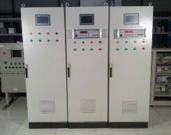
PLC control cabinet basics explain
What is a PLC control cabinet