Rotary encoders are widely used in industrial automation systems. A typical application of this type of Encoder is electrical machinery, where the encoder is connected to a rotating shaft to provide feedback to the control system. Although the encoder is primarily used for angular position and velocity measurement, other features such as system diagnostics and parameter configuration are also common. Figure 1 shows a motor control signal chain that uses an RS-485 transceiver and microprocessor to connect an Absolute Encoder (ABS encoder) slave and an industrial servo driver host to achieve closed-loop control of the AC motor. RS-485 communication links between servo drives and ABS encoders typically require high data rates and low propagation delay timing specifications up to 16 MHz. The maximum extension length of RS-485 cable is usually 50 meters, but sometimes it may be as long as 150 meters. For data communications, motor control encoder applications are challenging environments because electrical noise and long cables can affect the integrity of the RS-485 signal transmission. This article focuses on the key benefits of using ADI's 50 Mbps (25 MHz) ADM3065E RS-485 transceiver and ADSP-CM40x mixed-signal control processor for motor control applications. The ADM3065E RS-485 transceiver is designed for reliable operation in harsh environments such as motor control encoders, and has enhanced immunity and (IEC) 61000-4-2 ESD (electrostatic discharge) robustness. Immunity RS-485 signal transmission is a balanced, differential transmission that is inherently immune to interference. System noise is evenly coupled to each wire in the RS-485 twisted pair cable. The emission of one signal is the opposite of the other signal, and the electromagnetic fields coupled to the RS-485 bus cancel each other out. This reduces the system's electromagnetic interference (EMI). In addition, the enhanced 2.1 V drive strength of the ADM3065E enables higher signal-to-noise ratio (SNR) in communications. Adding signal isolation to the ADM3065E is easily accomplished with the ADuM141D. The ADuM141D is a quad-channel digital isolator that uses ADI's iCoupler® technology. The ADuM141D operates at data rates up to 150 Mbps, so it works well with the 50 Mbps ADM3065E RS-485 transceiver (see Figure 2). The Direct Power Injection (DPI) method measures the device's ability to suppress noise injected into the power supply or input pins. The isolation technology used by the ADuM141D has been tested and complies with the DPI IEC 62132-4 standard. The ADuM141D's immunity performance exceeds that of similar products. The ADuM141D maintains excellent performance over the entire frequency range, while other isolation products suffer from bit errors in the 200 MHz to 700 MHz band. IEC 61000-4-2 ESD Performance The ESD on the exposed RS-485 connector and cable from the encoder to the motor driver is a common system risk factor. The system-level IEC 61800-3 standard relating to the EMC immunity requirements of variable-speed electric drive systems requires IEC 61000-4-2 ESD protection of at least ±4 kV (contact)/±8 kV (air). The ADM3065E exceeds this requirement and provides ±12 kV (contact)/±12 kV (air) IEC 61000-4-2 ESD protection. Figure 3 shows the comparison of the 8 kV contact discharge current waveform with the Human Body Model (HBM) ESD 8 kV waveform in the IEC 61000-4-2 standard. As can be seen from Figure 4, the waveform shapes and peak currents specified by the two standards are different. The peak current associated with the IEC 61000-4-2 8 kV pulse is 30 A, and the corresponding HBM peak ESD current is less than one-fifth of this value, which is 5.33 A. Another difference is the rise time of the initial voltage spike. For the IEC 61000-4-2 ESD, the rise time is 1 ns, which is much faster than the 10 ns time associated with the HBM ESD waveform. The power value associated with the IEC ESD waveform is significantly greater than the corresponding value of the HBMESD waveform. The HBM ESD standard requires that the device under test (EUT) undergo 3 positive and 3 negative discharges, whereas the IEC ESD standard requires 10 positive and 10 negative discharge tests. The ADM3065E with IEC 61000-4-2 ESD ratings is more suitable for operation in harsh environments than other RS-485 transceivers rated for a variety of HBM ESD protection levels. EnDat communication protocol There are many communication protocols used by encoders, such as EnDat, BiSS, HIPERFACE, and Tamagawa. Despite the differences, encoder communication protocols have similarities in implementation. The interface to these protocols is a serial bidirectional pipe that complies with RS-422 or RS-485 electrical specifications. Although the hardware layers are the same, the software required to run each protocol is unique. The communication stack and the required application code are specific to the protocol. This article describes the hardware and software implementation of the host side of the EnDat 2.2 interface. Delay effect There are two types of delays: the first type is the transmission delay of the cable, and the second type is the propagation delay of the transceiver. The cable delay is determined by the speed of light and the dielectric constant of the cable and is typically 6 ns/m to 10 ns/m. When the total delay exceeds half a clock cycle, the communication between the master and slave will fail. In this regard, designers have the following options: * Reduce data rate * Reduce propagation delay * Provide delay compensation on the host side Option 3 can compensate for both cable delays and transceiver delays, and is therefore an effective way to ensure that the system can operate over long cables at high clock rates. The disadvantage is that delay compensation increases the complexity of the system. In systems where delay compensation is not feasible, or in systems where the cable is short, the use of a transceiver with a short propagation delay has clear advantages. The low propagation delay allows the clock rate to be higher and it is not necessary to introduce delay compensation in the system. Host implementation Host implementations include serial ports and communication stacks. The encoder protocol is not compatible with standard ports (such as UART) and it is not possible to use peripherals on most general-purpose microcontrollers. However, using the FPGA's programmable logic can implement dedicated communication ports in hardware and support advanced features such as delay compensation. Although the FPGA method is flexible and can be customized for specific applications, it has disadvantages. Compared with processors, FPGAs have high costs, large power consumption, and long time to market. The EnDat interface discussed in this article is implemented on Analog Devices' ADSP-CM40x, a processor developed for motor control drivers. In addition to peripherals for motor control, such as PWM timers, analog-to-digital converters (ADCs), and sinc filters, the ADSP-CM40x has a highly flexible serial port (SPORT). These SPORTs can emulate a variety of protocols, including encoder protocols such as EnDat and BiSS. Because the peripherals of the ADSP-CM40x are very rich, it can not only perform advanced motor control, but also interface with the encoder. In other words, there is no need to use an FPGA. Test setup The EnDat 2.2 test setup is shown in Figure 4. The EnDat slave is Kollmorgen's standard servo motor (AKM22) and the EnDat encoder (ENC1113) is mounted on the shaft. Three pairs of wires (data, clock, and power line) connect the encoder to the transceiver board. The EnDat PHY has two transceivers and a power supply for the encoder. One transceiver is for the clock and the other transceiver is for the data line. The EnDat host is implemented with the ADSP-CM40x combined with standard peripherals and software. Both the send port and the receive port are implemented using flexible SPORT. The EnDat protocol includes a variety of different length frames, but these frames are all based on the same sequence, as shown in Figure 5. First, the host sends a command to the slave, and then the slave processes the command and performs the necessary calculations. Finally, the slave sends the result back to the host. The transmit clock (Tx CLK) is generated by the processor ADSP-CM40x. Due to system delay, data from the encoder will be out of phase with the transmit clock before returning to the processor. To compensate for the propagation delay tDELAY, the processor also generates a receive clock (Rx CLK) which is delayed by tDELAY than the transmit clock. Having the receiving clock in phase with the data received from the slave is an effective way to compensate for transmission delays. The clock signal from the processor is continuous, and the EnDat protocol specifies that the clock can only be applied to the encoder during communication. At all other times, the clock line must remain high. For this purpose, the processor generates a clock enable signal CLK EN, which is sent to the ADM3065E data enable pin. After exactly two clock cycles (2T), the host starts issuing commands on Tx DATA. The command is 6 bits long, followed by two 0 bits. To control the data direction of the transceiver, the processor sets the Tx/Rx EN bit during transmission. While the slave is ready to respond, the system enters the wait state and the host continues to apply the clock, but the data line is invalid. When the slave is ready, the data line reception data is pulled high and then the response is sent immediately. After receiving an n-bit response, the host sets the CLK EN signal low to stop the clock. At the same time, the ENC CLK signal goes high. The data stream is a half-duplex type, and the ENC data graphs are the transmitted and received data streams drawn together. Experimental results Figure 6 shows the test results of the EnDat system. The test uses a clock frequency of 8 MHz and delay compensation is achieved by receiving the clock phase shift. The bottom signal is a command from the EnDat host. The command shown here is "Send Position", which is preceded by two 0s, followed by six 1, and finally by two zeros. There are 10 places in this order. The encoder's response is the third signal from the top. The merged data line is the second signal from the top. Finally, the top signal is the clock applied to the encoder. A manual pulse generator (MPG) is a device normally associated with computer numerically controlled machinery or other devices involved in positioning. It usually consists of a rotating knob that generates electrical pulses that are sent to an equipment controller. The controller will then move the piece of equipment a predetermined distance for each pulse. Manual Pulse Generator,Handwheel MPG CNC,Electric Pulse Generator,Signal Pulse Generator Jilin Lander Intelligent Technology Co., Ltd , https://www.jilinlandermotor.com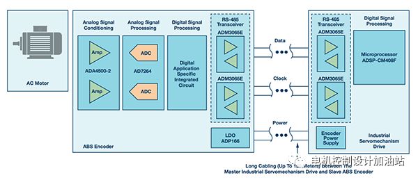 Figure 1. Using RS-485 to connect an absolute encoder slave and a servo driver host to achieve closed-loop control of the AC motor.
 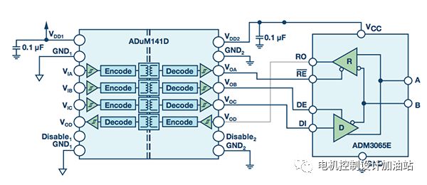 Figure 2. Signal isolated 50 Mbps RS-485 solution (simplified diagram, not all connections are shown).
 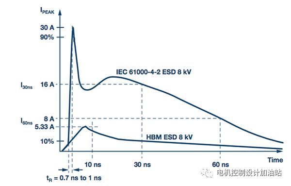 Figure 3. Comparison of IEC 61000-4-2 ESD Waveform (8 kV) and HBM ESD Waveform (8 kV)
 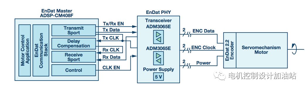 Figure 4. Experiment setup
 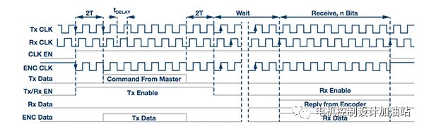 Figure 5. EnDat send/receive sequence
 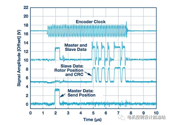 Figure 6. EnDat data exchange
The CNC handheld controller MPG Pendant with x1, x10, x100 selectable. It is equipped with our popular machined MPG unit, 4,5,6 axis and scale selector, emergency stop and reset button.