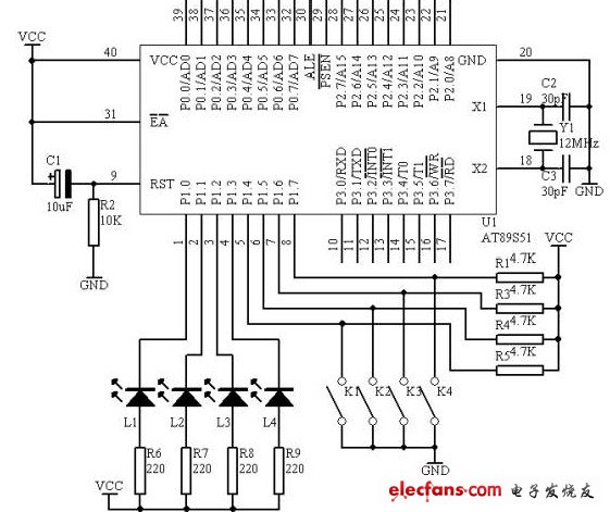
As shown in the figure below, P1.0 - P1.3 of AT89S51 MCU is connected to four LEDs L1 - L4, P1.4 - P1.7 are connected with four switches K1 - K4, and the status of the switch is reflected on the LED. . (The switch is closed, the corresponding light is on, the switch is off, and the corresponding light is off). 1 . Connect P1.0 - P1.3 in the "Microcontroller System" area to the L1 - L4 port in the "Eight LED Indicator Module" area; Glass surface material ,copper inside,screen touching wall switch Wenzhou Niuniu Electric Co., Ltd. , https://www.anmuxisocket.com
2 . Connect P1.4 - P1.7 in the "Microcontroller System" area to the K1 - K4 ports in the "4-way toggle switch" area.