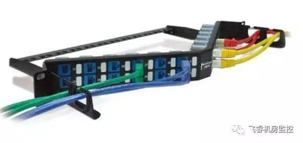
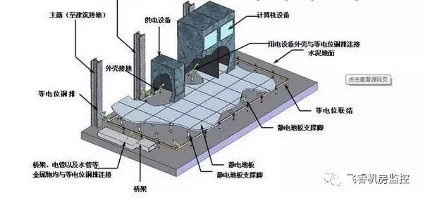
The advantages of the shielded wiring system are mainly reflected in its strong resistance to external electromagnetic interference and radio frequency interference. At the same time, it can also prevent the internal transmission signal from radiating energy to the outside world, and has good system security. For a shielded wiring system, to reflect its characteristics, we need to pay attention to the following two points in design and construction: 1. The function of the shielded cabling system requires the use of shielding products for all connected hardware, including: transmission cables, patch panels, modules and jumpers. 2. Shielded wiring system installation must be correct and well grounded. If the shielding layer of each connecting component of the transmission channel is discontinuous or poorly grounded, it may be worse than the transmission performance provided by the unshielded system. The first part of the shielded wiring system installation The installation of the shielded cabling system involves two main aspects: shielded cable termination and system grounding in the floor wiring closet and work area. For the particularity of the shielding system, it is necessary to ensure that the shielding layer of the cable has good contact with the shielding layer of the module and the distribution frame in a range of 360 degrees, instead of connecting at some points, and the shielding layer cannot be in the same strip. A break occurred in the middle of the link. Step 1: Use a special termination tool to remove the outer sheath of the shielded cable; Step 2: Separate the four pairs of twisted-pair core wires. Do not disassemble the core wire pairs. According to the color line order of the core wires indicated on the information module, pull a small corresponding core wire with both hands. Put the wires into the corresponding slots one by one with a little force; Step 3: After all the core wires are embedded, the core wire can be further pressed into the wire slot by a wire cutter. Align the edge of the wire tool with the wire slot and wire on the information module, and the excess wire outside the module is cut. Repeat this operation, and also connect the drain wire in the cable to the metal piece on the back of the module; Step 4: Insert the plastic dustproof piece of the information module into the twisted pair along the gap, and fix it on the information module, then cover the iron cover of the module and press it to complete the whole process of the module. Then put the prepared information module into the information outlet; Step 5: After the information module is created, you can of course test whether the connection is good. At this time, you can measure with a multimeter. Put the multimeter's gear position on the x10 resistance file, and touch one pin of the universal bead with the corresponding core wire of the other end of the network cable, and the other multimeter pen contact information module is snapped into the edge of the card slot of the corresponding color core wire (note It is not in contact with the core wire. If the resistance is small, it proves that the information module is well connected, otherwise the wire core is pressed with the wire clamp until it is clear. You can also use a professional tester, such as FLUKE, to select different screening test standards for different objects. A complete shielded cabling system installation requires shielding everywhere, a continuous, complete shield path to achieve the user's expectations. If a shielded system is chosen, in addition to the cable, the connectors, modules and other connectors need to be shielded, and then complemented by metal bridges and pipes. The principle of electrostatic shielding is to make the interference current flow into the earth through the shielded outer layer, so proper grounding of the shielding layer is very important. The second part is grounded Proper grounding of the shield is very important, otherwise it will not reduce the interference, but will increase the interference. Because when the grounding point is not arranged correctly, the grounding resistance is too large, and the grounding potential is unbalanced, grounding noise is generated, that is, a potential difference is generated at some two points of the transmission channel, thereby causing interference current on the metal shielding layer. It itself forms the largest source of interference, resulting in far less performance than unshielded transmission channels. Therefore, in order to ensure the screen effect, the shield must be properly and reliably grounded. The grounding fitting in the shielded distribution frame is a busbar for grounding, which can connect the shielding module through it to a unified grounding body to form a grounding channel in the distribution frame. There are two main types of grounding accessories for shielded patch panels: 1. Grounding accessories installed in the distribution frame The grounding fitting installed in the distribution frame has elasticity. When the shielding wiring system installation module is inserted into the distribution frame, the metal casing automatically forms a good connection with the grounding fitting, and the grounding work of the shielding module is completed. 2. Independent grounding accessories Separate grounding accessories can be converted into shielded patch panels with dedicated unshielded patch panels. These shielded modules typically contain a grounding interface for pluggable wiring. After the shield module is inserted into the patch panel, insert the strap in the grounding connector into the grounding interface of the shield module to form the grounding connection of the shield module. A grounding post should be installed on the distribution frame so that the grounding conductor from the cabinet can be attached to it. The traditional shielded distribution frame is grounded through metal posts in the cabinet, which is no longer used. The shield grounding of the patch panel can be as follows: 1. Each shielded distribution frame is connected to the bus bar of the cabinet through respective grounding wires to form a star-shaped grounding structure; 2. Install a grounding copper bar at the bottom of the cabinet and connect the grounding copper bar to the grounding pile (grounding copper bar) of the wiring closet (telecom room) using a separate grounding wire to form a star-shaped grounding structure between the grounding of each cabinet. ; 3. The cross-sectional area of ​​the grounding conductor should be greater than 6mm2; 4. The cold-welded soldering irons commonly used by electricians should be used at both ends of the grounding wire to avoid the short-circuiting of the wire ends; 5. In order to improve the bleed capacity of high-frequency interference signals, it is recommended that the grounding conductors need to be braided to meet the skin effect of high-frequency current with a larger surface area. In the installation of shielded wiring system, in addition to the need for high-quality wire and connectors, good construction skills and meticulous work attitude are essential. Pay attention to the details of the construction process, do a good job in the various grounding links in the shielding system, I believe that we can make a high-quality shielding project. Back Seat Headrest Pillow Phone Holder Back Seat Headrest Pillow Phone Holder,Samsung Tablet Car Holder Back Seat,Car Back Seat Organiser With Tablets,Car Back Seat Tablet Holder Ningbo Luke Automotive Supplies Ltd. , https://www.car-phone-holder.com
