1. Introduction to LED A light-emitting diode is a type of semiconductor diode that converts electrical energy into light energy, often abbreviated as an LED. Commonly used are diodes that emit red, green or yellow light. The reverse breakdown voltage of the LED is approximately 5V. Its forward volt-ampere characteristic curve is very steep, and a current limiting resistor must be connected in series to control the current through the tube. The current limiting resistor R can be calculated by: R = (E - UF)/IF Where E is the supply voltage, UF is the forward voltage drop of the LED, and IF is the general operating current of the LED. LED is widely used in various electronic circuits, home appliances, meters and other equipment to do power or level indication. 2, STM32 GPIO Introduction STM32F4 Each set of general purpose I/O ports includes four 32-bit configuration registers (MODER, OTYPER, OSPEEDR, and PUPDR), two 32-bit data registers (IDR and ODR), and one 32-bit/reset register (BSRR), 1 A 32-bit lock register (LCKR) and two 32-bit multiplexed function selection registers (AFRH and AFRL). GPIO can be configured in the following eight modes of operation: Floating input: This port is connected to the default by any high-impedance state. This setting is used more during data transmission. Pull-up input: Compared with the floating input mode, the pull-up input mode is only connected to a pull-up resistor in the upper part of the data channel. The resistance of this pull-up resistor is between 30K and 50K ohms. The CPU can be input at any time. The other end of the data register reads the level state of the I/O port. The advantage of this mode is that when we do not input anything, the processor will think that we have input a high level due to the internal pull-up resistor, which avoids the uncertain input. This port is input high by default. Analog function: The configuration of the analog input channel of the STM32 is very simple, and the signal enters the ADC module directly from the I/O port. At this point, all pull-ups, pull-down resistors, and Schmitt triggers are off, so the input data registers will not reflect the level state on the port, that is, the signal is not input in the analog input configuration. The data register, the CPU cannot read valid data on the input data register. This input mode allows us to obtain an external analog signal open-drain output: the open-drain output cannot directly output a high level, and the output of the open-drain output is equivalent to the collector of the triode. To obtain a high-level state, a pull-up resistor is required. Only then. Open-drain multiplexed output: The basic function of GPIO is normal I/O, and STM32 has its own function modules. The pins of these built-in peripherals are multiplexed with standard GPIOs, when used as function pins of these modules. It is called multiplexing. The open-drain multiplexed output function mode is different from the open-drain output mode in that the input of the output control circuit is connected to the output signal of the on-chip peripheral, that is, to the output of the multiplexed function. At this time, the output data register is The output channel is disconnected. Push-pull multiplexed output: The push-pull multiplexed output function mode is different from the push-pull output mode in that the input of the output control circuit is connected to the output signal of the on-chip peripheral, that is, to the output of the multiplex function. The output data register is disconnected on the output channel. In the iCore3 dual-core development board, a separate red, green and blue tri-color LED is connected to the STM32F407, and the current limiting resistor is 1K. Among them, the red LED is connected to the PI5 pin, the green LED is connected to the PI6 pin, and the blue LED is connected to the PI7 pin. In this experiment, three channels of three-color LEDs are driven by three GPIO ports of STM32, the GPIO is set to push-pull output mode, and the current is connected to the LED. The GPIO output high-level LED is off, and the GPIO output is low-level LED. Lights up, controlling the LED's on and off by controlling the level of the GPIO output. 1, the main function /* * Name : main * Description : --- * Author : ysloveivy. * * History * -------------------- * Rev : 0.00 * Date : 11/21/2015 * * create. * -------------------- */ Int main(void) { Int i; Led.initialize(); //Three color LEDs flash alternately While(1){ LED_RED_ON; LED_GREEN_OFF; LED_BLUE_OFF; For(i = 0;i < 10000000;i++); LED_RED_OFF; LED_GREEN_ON; LED_BLUE_OFF; For(i = 0;i < 10000000;i++); LED_RED_OFF; LED_GREEN_OFF; LED_BLUE_ON; For(i = 0;i < 10000000;i++); } } 2, GPIO initialization * Name : initialize * Description : --- * Author : ysloveivy. * * History * -------------------- * Rev : 0.00 * Date : 11/21/2015 * * create. * -------------------- */ Static int initialize(void) { GPIO_InitTypeDef GPIO_uInitStructure; //LED IO initialization RCC_AHB1PeriphClockCmd(RCC_AHB1Periph_GPIOI, ENABLE); GPIO_uInitStructure.GPIO_Pin = GPIO_Pin_5 | GPIO_Pin_6 | GPIO_Pin_7; //Initialize the IO port connected to the tri-color LED GPIO_uInitStructure.GPIO_Mode = GPIO_Mode_OUT; //Set the port to output mode GPIO_uInitStructure.GPIO_OType = GPIO_OType_PP; //Set the output type to push-pull output mode GPIO_uInitStructure.GPIO_PuPd = GPIO_PuPd_UP; // Pull-up output GPIO_uInitStructure.GPIO_Speed ​​= GPIO_Speed_100MHz; //Set the speed grade GPIO_Init(GPIOI,&GPIO_uInitStructure); //PI5, PI6, PI7, connected to three-color LED lights, set high level, the light goes out GPIO_SetBits(GPIOI, GPIO_Pin_5 | GPIO_Pin_6 | GPIO_Pin_7); Return 0; } Void GPIO_Init(GPIO_TypeDef* GPIOx, GPIO_InitTypeDef*GPIO_InitStruct) This function has two parameters. The first parameter is used to specify the GPIO group corresponding to the GPIO to be initialized. The value range is GPIOA~GPIOK. The second parameter is the initialization parameter structure pointer, and the structure type is GPIO_InitTypeDef. The structure is defined as Typedef struct{ Uint32_t GPIO_Pin; //Set IO port GPIOMode_TypeDef GPIO_Mode; //Set port working mode GPIOSpeed_TypeDef GPIO_Speed; //Set the speed grade of the port GPIOOType_TypeDef GPIO_OType; //Set the port type GPIOPuPd_TypeDef GPIO_PuPd; //Set up and down }GPIO_InitTypeDef; The three-color LED connected to the ARM on the iCore3 dual-core board (labeled ARM·LED on the PCB), red, green, and blue are alternately lit. Wireless Barcode Scanner,Bluetooth Barcode Scanner,Wifi Barcode Scanner,Portable Barcode Scanner ShengXiaoBang(GZ) Material Union Technology Co.Ltd , https://www.sxbgz.com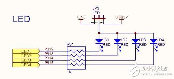
STM32 GPIO output programming example lighting three-color LED
I. Overview: