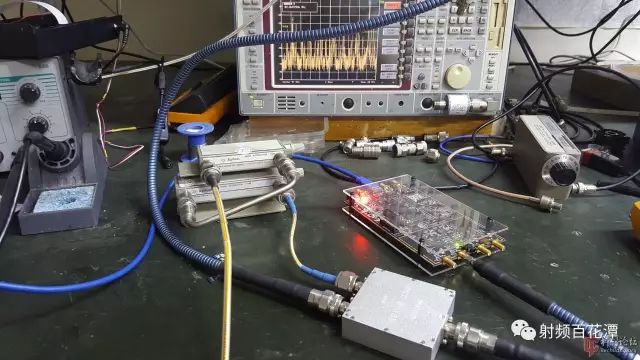
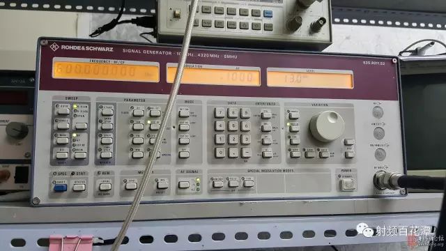
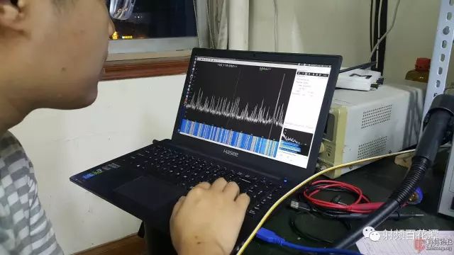
In narrowband applications, zero-IF software radio chips have become very popular, represented by the Analog Devices AD9361. The narrowband application mentioned here means that its tuning bandwidth is relatively narrow, such as working in the 700-1200MHz range. If working in broadband applications - such as handheld broadband receivers - the frequency range is required to cover 50M-6GHz. In such a wide range, what is the actual performance without complicated pre-selection? I used to listen to a master who said that it was a mess, and there were many pits. Not only was it easy to die, but there were still many false signals, so I was discouraged and honestly made multiple frequency conversion superheterodyne + digital DDC schemes. After all, as an instrument-level application, it is consistently disdaining this zero-IF scheme. Recently, we need to make a broadband product with ganyi. Because the cost is urgent, I suddenly feel that I should personally check whether this thing is really like the disdain of some masters. If it can be used, it will not save trouble. Here is a post, taking AD9361 as an example to explore some simple performance issues of zero-IF receivers. The level is limited, and only need to know about it, so it is not very standard, just chat, welcome to vomit, pick the thorns and spank. The first measured is about anti-blocking ability. This is an indicator that is worried about more. Test program: Definition: A receiver receives a signal at the A frequency and has a strong interference at the B-band outside the band and also enters the receiver. When the strength of the interference B is so strong that the receiver's ability to receive the signal A drops by 6 dB (one time down), the strength of the signal B is the blocking level of the receiver. The outdoor antenna enters the AD9361 via a mechanical attenuator and combiner. The strong signal source also enters the 9361 through the same combiner, continuously increasing the output level of the strong signal source, and measuring the level value when the AD9361 is blocked. The board of the AD9361 is a B210 compatible board made by BA3CE. Due to the loss of the combiner, cable, etc., the signal (interference) intensity entering the test board is calibrated before testing. If you need to test multiple frequencies, you need to recalibrate each time you change the frequency. In theory, the sampling of the AD9361 is also subject to amplitude calibration, but it is quite accurate. Since the decline in acceptability is a relative value, the absolute level measured by the AD9361 is not calibrated. Instrumentation required: step attenuator, signal source, spectrum analyzer or test receiver, combiner, necessary connecting cable. The spectrum analyzer is used to calibrate the intensity of the B signal (generated by the source) that reaches the test board. There was no deliberate photo taking during the test, just put a few. This is the way to connect, the silver-white thick Chinese style is the combiner. The signal source of the blue armor wire that enters the field of view from above, and the golden wire of the attenuator is connected to the outdoor antenna. Still using this signal source Use an SDR software to display the spectrum. The warmonkey is operating the software. Test Results: 1. Connect the outdoor antenna and attenuate it to 0dB. Regardless of the frequency at which the software is set, the 9361 is obviously overloaded, showing a lot of noise boost and a lot of false signals. But here is the city center and close to the radio station, the overload is justifiable. 2. Attenuation is turned on to 20dB to completely eliminate the overload. The B210 does not seem to send out the overload alarm data built into the 9361, which requires manual judgment. The method of judging is to continue to increase the attenuation, and the amount of change in signal strength is substantially consistent with the increased amount of attenuation. 3. When setting B210 to receive FM broadcast, at any frequency below 3 GHz (we randomly select several tests), as long as the interference of -2dBm is injected, the strength of the received broadcast signal in the FFT result can be reduced. 6dB. At this point the gain has been adjusted to the lowest and there are no preamplifiers. If you increase the gain, the blocking performance will definitely drop, but this time you did not test it carefully. 4. Whether it is a weak signal or a strong signal, when the interference is blocked, the trend of reduction is the same. 5. Keep the B210 setting the same as the one in the above test. The noise floor is about -105dBm. Explanation of the results: In layman's terms, just find a frequency to transmit interference, as long as the intensity of the leak into the receiving port reaches -2dBm, the sensitivity of the AD9361 will drop by 6dB. If you don't add a preselector, it's really easy to get blocked. In fact, -2dBm is already a good indicator, and the FFT graph can still maintain a dynamic range of about 90dB (actual 100dB, but slightly compressed), and the performance is good. Although there are some unsatisfactory places, it is not as bad as imagined. Netizen stick: It seems that the dynamic range of a common triode. It is awkward to not add a bandpass filter. Since traditional analog reception is still so useful, it should be possible to develop a universal receiver module. For example, detection module, AGC module, 455KHz mid-release module, 10.7MHz mid-range module, high-IF module, mixing module, town module...etc. This development is very easy, and a receiver can be spelled out in a few minutes. Standardized modules, indicators are also easy to control. You can also take extra to sell to amateurs. Schrödinger's cat: Module splicing is a technology used by devices 30 years ago. The new devices are currently highly integrated and low power. These modules are generally replaced by various types of integrated chips, but complex wiring and system design simulations are still required, which is not very cost-effective as a product-level application. All integrated chips such as the AD9361 integrate all functions in a single chip, and all of them can be called by software. The development environment and open source code are mature, and it is quite advantageous in general RF application scenarios. It's also a good thing to add a few peripherals to expand its functionality and frequency range with some special design techniques, and it's cheap. Sewing Machine Motor,Dc Motor Sewing Machine,Industrial Sewing Machine,Brushless Servo Motor LISHUI SHUANGZHENG MOTOR CO.,LTD. , https://www.szservomotor.com

