This paper introduces the inverter module made of a single IGBT tube or double tubes and its method of measuring the profit and judging the good and bad. FETs have the advantages of fast switching speed and voltage control, but they also have the disadvantages of large turn-on voltage drop and small voltage and current capacity. The bipolar devices have the opposite characteristics, such as current control, low turn-on voltage drop, large power capacity, and so on. The origin of IGBT tubes, or IGBT modules, is based on this. From the structural point of view, similar to the compound amplification tube we are familiar with, the output tube is a PNP type transistor, and the excitation tube is a field effect tube, and the drain current of the latter forms the base current of the former. Magnification is the product of two tubes. The equivalent circuit and symbol of IGBT tube are shown in Fig. 1. 1. Measuring this "three-phase rectifier bridge" is not normal, then the module is damaged: Wireless Charger Car Phone Holder Wireless Charger Car Phone Holder,In Car Phone Holder Wireless Charger,Car Phone Holder And Charger,Phone Car Mount With Wireless Charger Ningbo Luke Automotive Supplies Ltd. , https://www.nbluke.com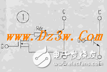
The pin functions of commonly used IGBT single and dual tube modules (CM200Y-24NF) are shown in Figure 2. 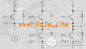
In practice, the module can be roughly measured before repairing and dismantling, and it is judged to be good or bad. Taking Figure 3 as an example, the 4, 5, and 6 terminals are the U, V, and W output terminals of the inverter, and 22 and 24 are the P (+) and N (-) terminals of the internal DC main circuit of the inverter, respectively. After finding these 5 terminals, you can use the digital or analog multimeter to test the inside. All three terminals U, V, and W have positive and negative resistances for the P and N terminals. When the IGBT tube is normal, the resistance between the C and E poles is infinite, and only the forward and reverse resistances of the 6 diodes connected in parallel on the tube can be seen. If the 4, 5, 6 terminals are regarded as three-phase AC input terminals, the six diodes are equivalent to a three-phase rectifier bridge circuit. It is possible to use a side-eating and a two-phase rectifier bridge method.
2. It is normal to measure this "three-phase rectifier bridge" and it is still not certain that the module is good. The main circuit board of the frequency converter should be switched on for further measurement and verification
The article explains the principle of IGBT module and measurement judgment method
GBT module principle and measurement judgment method