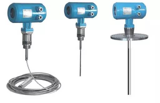
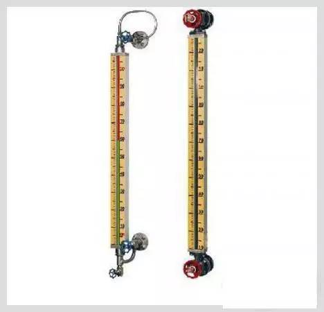
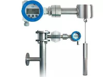
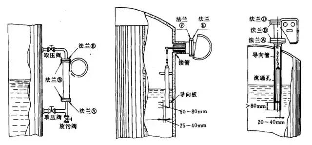
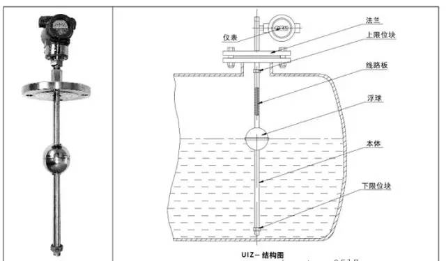
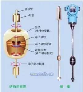
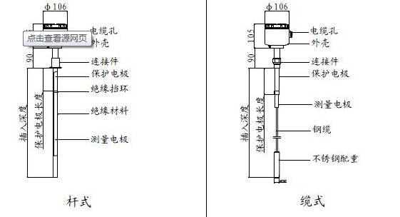
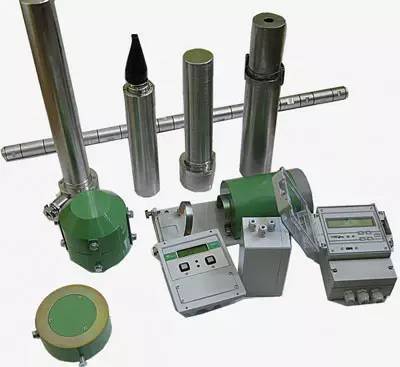
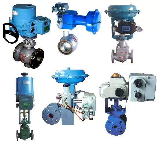
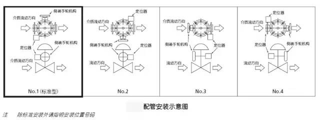
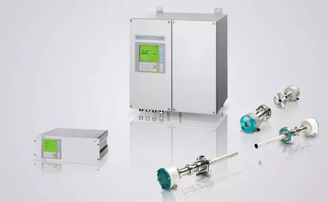
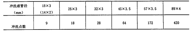
Level measuring instrument The general arrangement of level measuring instruments is as follows: 1. The position of the meter connector (nozzle) of the level measuring instrument should avoid the impact of entering the equipment. 2. The observation surface of the instrument should face the operating channel, and there should be no objects obstructing the maintenance of the instrument around. The level measuring instrument should be installed at one end of the platform, or the platform should be widened. 3. If the meter connector (nozzle) of the level measuring instrument is at the bottom of the device, it should extend 100mm into the device. 4. When measuring the interface level, the upper instrument connector (nozzle) of the level measuring instrument must be located in the liquid layer. 5. When several level gauges are used in combination, the connecting pipe installation type should be adopted. The installation requirements for the glass plate (tube) level gauge are as follows: 1. When measuring the same liquid with a glass plate (tube) level gauge and a float (float) level gauge, the measurement range of the glass plate (tube) level gauge should include the measurement range of the float (float) level gauge. 2. When several level gauges are used in combination, the two adjacent level gauges should overlap by 150~250mm in the vertical direction, and the horizontal spacing should be 200mm. 3. When several level gauges are used in combination, an external connecting pipe should be used for installation. The two ends of the connecting pipe should be equipped with a shut-off valve. The glass plate (tube) level gauge is installed on this pipe, and a shut-off valve is not required. The installation requirements for the outer float level gauge are as follows: 1. Shut-off valves should be installed at both ends of the level gauge. 2. The middle position of the measuring range of the level gauge. 3. For top-bottom flange type liquid level gauges, the distance between the upper and lower instrument connectors (nozzles) should be at least 500mm larger than the measuring range. The installation requirements for the inner float level gauge are as follows: 1. The normal liquid level should be in the middle of the float. 2. When the liquid level fluctuates greatly, an anti-wave tube should be added. The installation requirements of the internal float level gauge are as follows: 1. The horizontal centerline of the mounting flange of the liquid level gauge should be consistent with the normal liquid level. 2. There should be no obstacles within the range of the floating ball, and anti-scour plates should be added in the occasions where the logistics impact is greater. The installation requirements of the magnetostrictive level gauge are as follows: 1. The magnetostrictive liquid level gauge should be installed on the top of the container or the top of the connecting pipe drawn from the side of the container. 2. The magnetostrictive level gauge installed on the top of the dome tank or spherical tank should adopt flange installation, and the inner diameter of the flanged instrument connector (nozzle) should be larger than the diameter of the float. 3. When installed on the connecting pipe outside the container, the inner diameter of the connecting pipe should be larger than the outer diameter of the float, and the connecting pipe should be made of non-magnetic materials (such as stainless steel, aluminum or alloy). The installation requirements for ultrasonic and microwave (radar) liquid (material) level gauges are as follows: 1. When measuring liquid level, it is advisable to detect and install vertically downwards. 2. When measuring the material level, the ultrasonic or microwave beam should point to the discharge port at the bottom of the silo. 3. The distance between the center of the ultrasonic or microwave beam and the container wall should be greater than the beam radius at the lowest liquid (material) level calculated from the beam angle and measurement range. 4. The beam path of ultrasonic or microwave should avoid the spray range of the container feed stream. 5. The beam path of ultrasonic or microwave should avoid stirrers and other obstacles. 6. The installation of ultrasonic or microwave liquid (material) level gauges should also meet the requirements of the manufacturer. The installation of guided wave radar and capacitive level gauge should meet the following requirements: 1. The level gauge should be installed on the top of the storage tank to avoid collision with the movable parts in the equipment; when the medium in the equipment fluctuates drastically, the probe (probe) should be fixed with a through-hole protection tube. 2. When the level gauge is installed on the connecting pipe outside the equipment, the following requirements should be met: a) The length of the probe (probe) should include the upper and lower measuring dead zones, and its end should be at least 50mm lower than the center of the lower connecting port of the connecting pipe; b) Guided wave radar liquid level timing with double-rod probe, the diameter of the connecting pipe is not less than 80mm; Guided wave radar liquid level timing with single-rod probe, the diameter of the connecting pipe is not less than 50mm. 3. When the cable probe type guided wave radar level gauge is used to measure the large liquid level, the cable probe should be straightened and fixed at the bottom of the equipment. When the liquid level fluctuates sharply, it should be fixed with a through-hole protective tube. 4. When the temperature of the measured medium is high, the transmitter should be installed separately. 5. The installation of guided wave radar and capacitive level gauge should also meet the requirements of the manufacturer. The installation of the hydrostatic liquid level measuring instrument should meet the following requirements: 1. The distance between the instrument connector (nozzle) of the single-flange level gauge and the bottom of the tank should be greater than 300mm, and it should be in an orientation that is easy to maintain. 2. The installation height of the double-flange remote-transmission differential pressure level gauge should not be higher than the lower pressure-taking flange port on the container, and the zero point and negative migration amount should be accurately calculated: the conductive capillary should be fixed with angle steel or steel pipe, and the environment Thermal insulation measures should be taken in places with large temperature changes. 3. The installation of measuring liquid level with a differential pressure transmitter should meet the following requirements: a) The distance between the connection heads (nozzles) of the upper and lower pressure measuring instruments should be greater than the required measurement range; the distance between the connection heads (nozzles) of the lower pressure measuring instruments and the bottom of the tank should not be less than 200mm, and avoid the liquid extraction outlet: upper pressure The instrument connection head (nozzle) should avoid the gas jet inlet, if it cannot be avoided, anti-flushing measures should be taken; b) When measuring the liquid level of volatile or condensable media, add an isolation tank on the negative pressure side (gas phase) or add isolation tanks on both sides of the positive and negative pressure, and accurately calculate the zero point and negative migration; c) When measuring the liquid level of the steam boiler drum, a temperature self-compensating balance vessel should be installed, and the pressure guiding tube should be heated and insulated. 4. When using the plug-in back-blowing method to measure the liquid level, the end of the inserted pressure guiding tube should be at least 200mm away from the bottom of the tank and cut into a slope. Installation of radioactive level meter The installation of the radioactive level meter should be carried out in strict accordance with the requirements of the manufacturer and comply with the relevant health and safety protection regulations of the People's Republic of China. Installation of steel belt level gauge and buoy level gauge The installation of the steel belt level gauge and the buoy level gauge should meet the requirements of the manufacturer. Control valve The installation position of the regulating valve is specified as follows: 1. The installation position of the regulating valve should meet the process requirements and be easy to install, maintain and operate. 2. The regulating valve should not be installed on the pipe trench or pipe rack. If it must be installed at a high place, a platform should be added. 3. If the regulating valve is equipped with auxiliary devices such as an accident gas source tank, a hand wheel, a lock valve, etc., there should be room for installation and operation. 4. The regulating valve should be close to the relevant local indicating instrument. The installation dimensions of the regulating valve are as follows: 1. The distance between the bottom of the control valve and the ground or platform surface should be greater than 250mm. For single and double-seat control valves with reversed valve cores, it is advisable to leave a space below the valve body to draw out the valve core. 2. The clearance distance between the top and the bypass pipeline should be greater than 200mm. The up and down positions of the regulating valve and the bypass valve should be staggered. The piping requirements of the control valve are as follows: 1. Set the shut-off valve and bypass valve of the regulating valve according to the process requirements and the special needs of the instrument. 2 The shut-off valve and bypass valve may not be installed if one of the following conditions is met: a) Operating conditions are not bad (clean medium with temperature not higher than 225℃, pressure not higher than 0.1MPa), regulating valve with handwheel with diameter greater than or equal to 100mm that controls non-important parameters; b) Sequence control regulating valve; c) Emergency stop interlock valve; d) Butterfly control valve with a diameter greater than 350mm; e) Three-way regulating valve; f) The steam regulating valve of the steam turbine pump driven by a backup motor; g) Places where the leakage of hazardous media (such as hydrofluoric acid, phenol, etc.) needs to be reduced. 3. For regulating valves with a diameter less than 25mm, the regulating valve can be installed above the bypass. The piping requirements of the actuator are as follows: 1. The regulating valve that makes the pneumatic actuator act quickly by venting. It should be equipped with a solenoid valve with a minimum operating pressure difference of zero. 2. When the signal is interrupted and the air source (or other power source) is interrupted, the actuator should keep the valve in a safe process position; for the double-acting cylinder actuator without self-reset capability, an accident air source tank should be installed. 3. Pneumatic diaphragm-type butterfly valves with large diameters or requiring quick action, or the adjustment signal gas circuit of the adjustment valve should be equipped with a pneumatic power amplifier and a quick exhaust valve. 4. The air supply piping of the pneumatic control valve should meet the following requirements: a) In places where the regulating valve is installed in a concentrated position, the air source can be filtered and decompressed; b) In places where the installation positions of the regulating valves are scattered, the air source to each valve should be filtered and decompressed separately; c) The air source of the cylinder gate valve should be filtered and decompressed separately and equipped with an oil mist device. 5. The power oil piping of hydraulic cylinder type actuator should meet the following requirements: a) The power oil system should be equipped with two sets of filters that are backup to each other; b) A relief valve should be installed at the highest point of the hydraulic system; c) The hydraulic system should be equipped with energy storage and backup automatic charging equipment. Industrial process analysis instrument The location of the sampling point should meet the following requirements: 1. The sample at this point can timely and accurately reflect the change of the measured parameter of the process fluid, and it is a measurable process fluid. 2. The process lag time between this point and the process correction point (usually a regulating valve, heating or cooler) is short. 3. Can provide clean and dry samples. 4. Appropriate sample pressure and temperature can be obtained. 5. Easy to access and maintain. 6. The head of the sampler should be extended to the center of the pipe, and the sampling port should face away from the sample flow direction. 7. The sampling point should be taken at the top or side of the process pipeline, not at the bottom of the process pipeline. The location of the analytical instrument should meet the following requirements: 1. Try to be as close as possible to the sampling point for easy access and maintenance. 2. Try to avoid the following occasions: a) The influence of thermal equipment or pipelines; b) The impact of shock or vibration; c) Where mechanical damage may occur; d) The occasion of strong electromagnetic interference. The installation requirements of the sampling system are as follows: 1. The material of the sampling system should meet the following requirements: a) Does not react with the sample; b) Do not extract components from the sample; c) Do not allow impurities to enter the sample or leached substances from the sampling system components to enter the sample through penetration or diffusion. 2. The piping design of the sampling system should meet the following requirements: a) The piping and pipe fittings of the sampling system should be degreasing, degreasing and decontamination treatment, without mechanical damage and leakage; b) On the premise of ensuring the required sample flow rate of the analyzer, the capacity of each component and tube of the sampling system should be minimized; c) As long as the pipeline pressure drop is allowed, the sample flow rate in the sampling system should be as high as possible; d Measures of heat insulation, heat tracing or cooling shall be adopted to ensure that the sample does not undergo phase change or reaction in the sampling system; e) When the process system is under negative pressure operation, the pumping method should be used for sampling; f) When the process stream contains granular or powdered catalyst, the sampling pipeline should be equipped with dust removal, filtration and back-blowing measures. 3. The sampling system should be equipped with a fast sampling loop, except for the following conditions: a) The analyzer is installed directly at the sampling point or close to the sampling point; b) Analyzing instrument for analyzing gases that can be vented directly (such as air, flue gas, etc.); c) Analyze water analysis instruments that can be directly discharged into the sewage system. 4. The fast sampling loop should send the samples taken from the process materials back to the process system. The power of the sample flow in the fast sampling loop should adopt the following methods: a) The differential pressure between the sampling point and the sample return point on the process pipeline; b) Mechanical pumps for sampling and returning samples (or gas or steam jet pumps). 5. The disposal of waste samples after analysis that cannot be economically sent back to the process system should meet the following requirements: a) It is not allowed to discharge hydrocarbons and chemical liquids on-site, and a dedicated sample recovery system should be set up; b) Water samples that meet the sanitary discharge standards can be discharged into the underground rainwater discharge system; c) Gases that meet the sanitary emission standards can be vented on-site; d) A small amount of light hydrocarbon gas or hydrogen can be introduced to a high place and discharged into the atmosphere, so that it can diffuse rapidly to below the lower limit of the explosive gas mixture; e) Toxic gas shall be discharged to a safe place by measures, and shall not be directly discharged into the atmosphere on the spot. The sample processing system should have some or all of the following functions: 1. Decompress or pressurize the sample to the inlet pressure required by the analyzer. 2. Decrease or increase the temperature of the sample to the inlet temperature required by the analyzer. 3. Increase the temperature of the sample to make the gas at least 10°C higher than its dew point to prevent condensation of high-boiling sample components; make the liquid sample at least 20°C higher than its freezing point to prevent crystal precipitation. 4. Heat and vaporize the liquid phase sample into the gaseous sample required by the gas phase analyzer. 5. Use a separator, aggregator or a dryer to remove non-sample moisture. 6. Filter out impurities and solid particles in the sample. The installation of the analyzer should meet the following requirements: 1. The analyzers for remote sampling should be installed relatively centrally in the on-site analyzer cabinet, analyzer shed or automatic analyzer room. 2. The automatic analyzer room should have the following functions: a) In cold areas, there should be heating and heat preservation facilities; b) Cooling facilities should be provided in hot areas; c) Good ventilation or forced ventilation facilities; d) The structural materials of the automatic analyzer room should not produce factors that affect the stable operation of the analyzer or factors that affect safety; e) The automatic analyzer room should have water supply and sewage measures; f) Easy for operators to enter and maintain; g) Equipped with installation facilities for standard sample cylinders; h) The indoor power supply, air supply, and steam supply of the automatic analyzer should be well designed and well-lit. 3. When combustible gas or toxic gas samples are introduced into the automatic analyzer room, a flammable gas or toxic gas detection and alarm instrument should be installed. 4. The exit position in the automatic analyzer room should be such that the staff can safely evacuate in the event of an emergency in the installation area. 5. The automatic analyzer room should be manufactured and installed internally by a professional manufacturer. 6. The installation location of the automatic analyzer room should meet the following requirements: a) It should be placed in a non-explosive hazardous location. If it is located in an explosive area of ​​Zone 1 or 2, corresponding explosion-proof measures must be adopted; b) The automatic analyzer room should be located near the pipe gallery. Try to shorten the distance between sampling points and public works; c) The automatic analyzer room should avoid the seismic source that can cause the indoor vibration amplitude to be greater than 0.1 lm m and the frequency to exceed 25 Hz, otherwise, vibration reduction measures should be taken; d) The automatic analyzer room should not be located in a place that causes continuous strong magnetic field interference to the analyzer; e) The location of the automatic analyzer room should be convenient for patrol inspection, operation, maintenance, and overhaul. Design of the electrical wiring of the analyzer The electrical wiring design of the analyzer should meet the requirements of the relevant explosion-proof regulations, and measures should be taken to avoid electromagnetic interference and interference from the power supply to the signal. Instrument valves and pipe fittings The type of valve on the pressure pipe of the instrument is specified as follows: 1. Generally, socket-welded valves should be used, and other types of valves can also be used. 2. If there is liquid in the pressure guiding tube, a stop valve should be used as a vent valve at the highest point of the pipeline. 3. Use gate valve, ball valve or shut-off valve as drain valve at the lowest point of pressure guiding pipe. 4. The valve material should be carbon steel or stainless steel, and other materials can also be selected according to the process conditions. The selection of pipe fittings on the pressure guiding tube of the instrument is as follows: 1. Elbow, straight, three-way or four-way joints should be connected by socket welding. 2. There should be no more than 3 detachable joints on the pressure pipe. The detachable joints should be connected by thread or high-quality ferrule. 3. The material of the pipe fittings should be equal to or better than that of the pressure guiding tube. Pneumatic signal pipeline and air source pipeline: 1. The air supply pipe should be led out from the upper or side of the main (branch) pipe and equipped with a shut-off valve. The shut-off valve of the air supply pipe should be a threaded gate valve or a ball valve. 2. An air source valve should be installed where the air supply pipe leads to the instrument. 3. The valve on the gas supply pipeline should be made of metal, and brass can be used indoors, carbon steel or stainless steel valves should be used outdoors and in harsh environmental conditions; the pipe fittings and valves on the pneumatic signal pipeline should be made of stainless steel. 4. Each local pneumatic instrument should be equipped with a small filter pressure reducing valve. 5. The pipe fittings and valves on the gas supply pipeline should adopt threaded connection. 6. The pipe fittings on the pneumatic signal pipe should be connected by a ferrule. Backflushing and flushing system of the instrument The requirements for the back-blowing system of the instrument pressure pipe are as follows: 1. The back-blowing system is mainly used for the liquid level measurement of the gas-blowing method and the measurement of fluidized bed pressure and differential pressure. It is advisable to use purified compressed air, nitrogen or dry desulfurization gas as the back-blowing gas. 2. The blowing point should be as close as possible to the shut-off valve, and the flow-limiting orifice or rotameter and the shut-off valve should be used to limit the amount of back blowing. a) The back-blowing pressure (absolute) should be at least twice the pressure of the measured medium (absolute); b) The amount of back-blowing gas should be determined according to the blowing speed. The pressure and differential pressure of the fluidized bed are measured, and the blowing speed is 1m/s. For general flow, liquid level and pressure measurement, the blowing speed is 0.2~ 0. 3m/s. 3. In order to prevent the air source from being blocked, the following measures should be taken: a) Set up public or individual filters; b) A check valve should be installed on the blowing pipeline. According to the specific piping conditions, several blowing points can share a check valve, or install a check valve on a platform; c) The back blow gas system of the fluidized bed (such as the reactor and regenerator of the catalytic cracking unit) should be separated from the instrument gas supply system, and the blow pipe should have a vertical pipe above the blow point, from top to bottom Blow. The requirements for the flushing system are as follows: 1. The flushing fluid system is mainly used to measure the occasions of high viscosity, easy to solidify, easy to coke and containing solid impurities and other media. The flushing fluid should not affect the quality of the measured medium and corrode the instrument. The flushing fluid can be selected from the medium with a certain pressure in the process itself (such as top reflux, solvent Etc.) An independent flushing system can also be set up. The flushing fluid main pipe should be equipped with a filter and a low-pressure alarm device, and the flushing fluid tank should have level control and high and low level alarms. 2. The pressure of the flushing fluid should be stable and greater than the maximum operating pressure of the measured medium. 3. The flushing fluid pipeline of each measuring instrument should be equipped with a stop valve, a check valve and a shut-off valve to adjust the flushing fluid volume, and a rotameter should be installed to indicate the flushing fluid flow. 4. In the continuous flushing system, the amount of flushing fluid is estimated and the pipe diameter is selected: a) The flow rate of the flushing fluid should be 0.06m/s. During continuous flushing, the flushing fluid consumption of the orifice plate flow meter (pressure taking hole 2X Φ8) is 2 X 0.015m3/h; the pressure meter (pressure taking hole Φ12) is 0.025m3/h; Differential pressure type liquid level instrument (pressure hole 2X Φ12) is 2 X 0.025m3/h; b) The circulating volume of the flushing fluid should not be less than 3 to 5 times the calculated consumption; c) The diameter of the flushing fluid can be selected according to Table 1. Table 1 Diameter of flushing fluid Note: Calculated based on a flushing point consumption of 0.03m3/h. Explanation of words The terms that require strictness in the provisions of this specification are described as follows: (1) The expression is very strict, and the words that must be done like this: Use "must" as positive words; The negative word uses "forbidden." (2) Words that indicate strictness, which should be done under normal circumstances: Use "should" as positive words; The opposite term uses "should not" or "shall not". (3) Words that indicate that a slight choice is allowed. When conditions permit, the first words to do this are: Use "宜" as the positive word; The negative word is "unfavorable". Indicates that there is a choice, and this can be done under certain conditions. Use "Yes". Power Inverter,Pure Sine Wave Inverter,300W Power Inverter,Mini Power Inverter GuangZhou HanFong New Energy Technology Co. , Ltd. , https://www.gzinverter.com