Many homes today have home appliances such as televisions, VCDs, video recorders, game consoles, and even video cameras and DVDs. If the RF signal of the above-mentioned home appliance is forwarded by a TV signal transmitter and is received by a television set (within a family room) of about 30 meters, the connection of the cable can be omitted, and many more inconveniences can be eliminated. The console is watched in different rooms. This TV signal transponder is like a small home TV station. The following is a TV signal repeater, which has the characteristics of simple circuit, low cost, and easy production. Shenzhen GEME electronics Co,.Ltd , https://www.gemesz.com
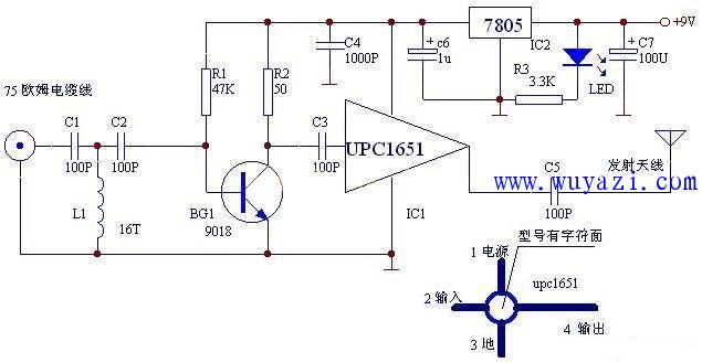
The circuit and working principle circuit are shown in the following figure: The working principle of this circuit is that the RF signal is sent to the high-pass filter with C1, L1 and C2 via the 75 ohm RF cable, and the frequency below 45MHz is filtered out, then The preamplifier consisting of a transistor such as a transistor 9018 is amplified and then sent to the upc1651 by the capacitor C3 for power amplification, and the output signal is transmitted through a whip antenna of about 60 cm. The 7805 and other components constitute a voltage regulator and power supply to provide 5V power for the upc1615.