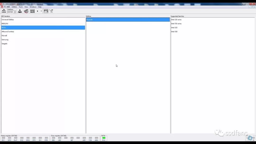
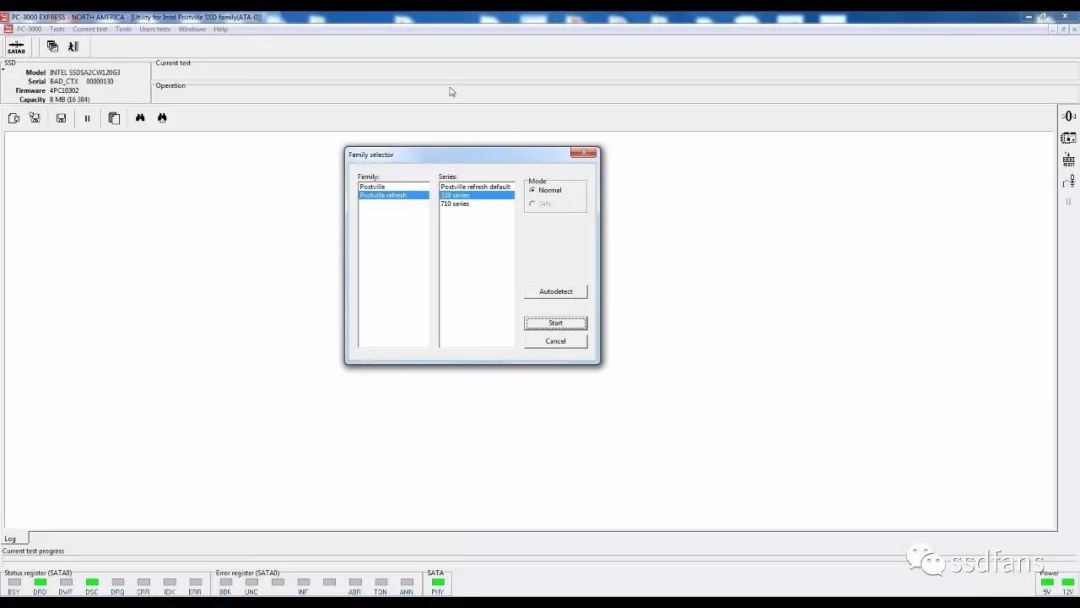
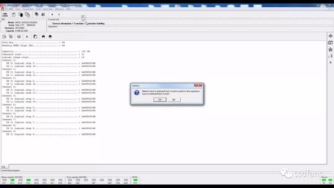
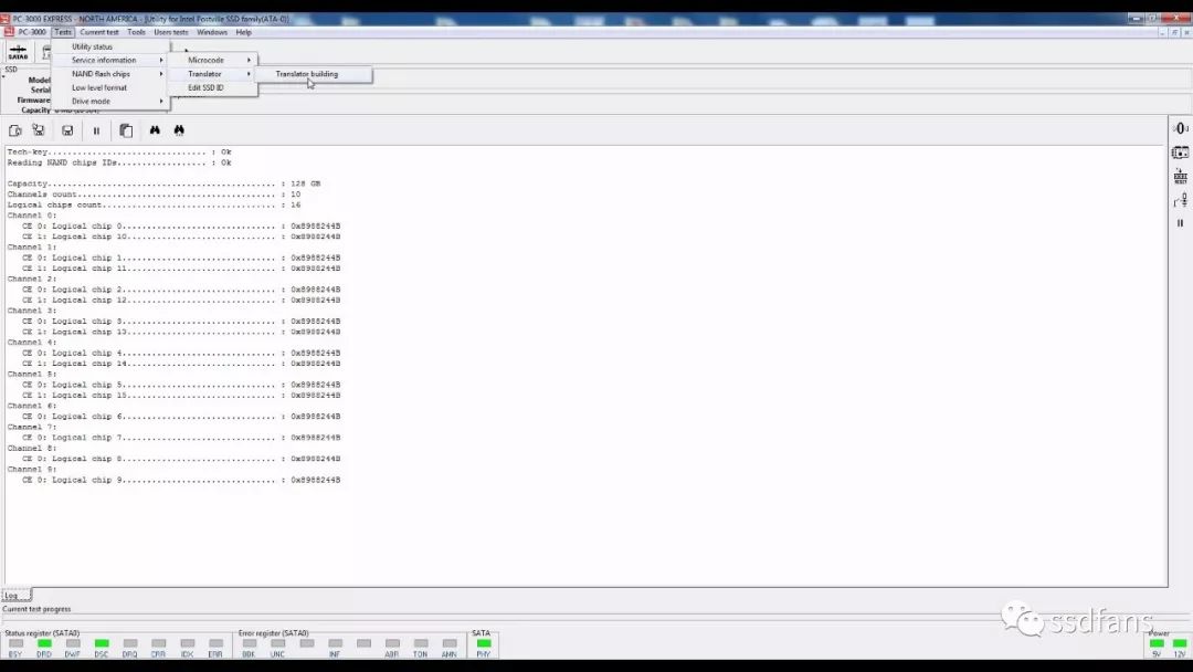
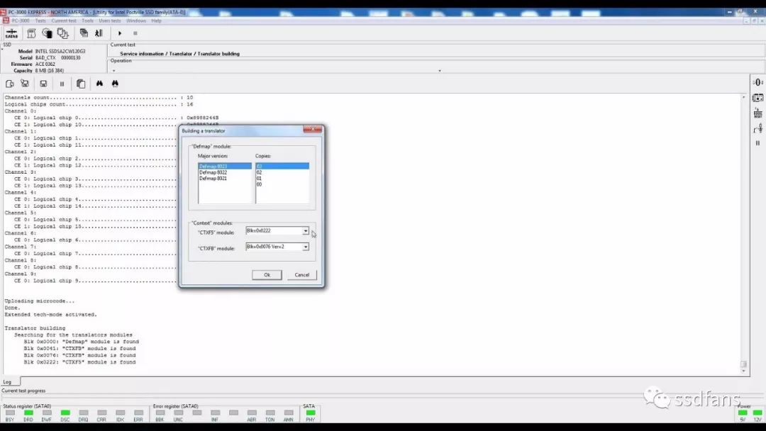
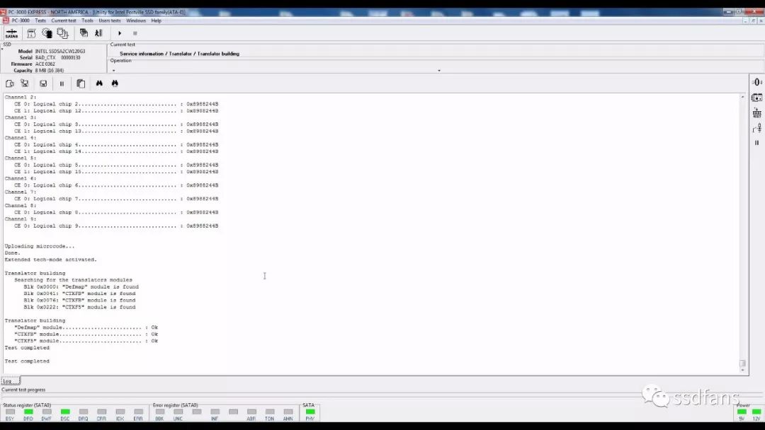
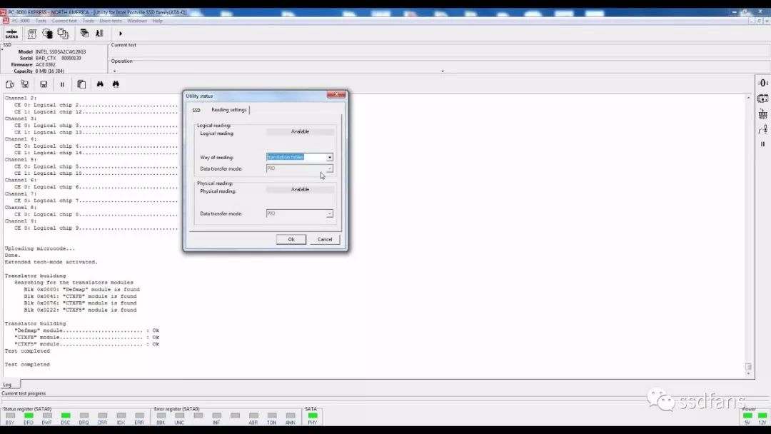
1. Support family series and general information 1.1 Support Family Series PC-3000 SSD 2.4.5 as an example, currently supports the following IntelPostville family IntelX18; Intel X25; Intel 320; Intel 710; 1.2 G2 and G3 Family General Information Intel usually represents its SSD series with a certain code. Therefore, the X25-M and X18-M series of drives are codenamed Postville, and the 320 series is Postville Refresh. The Intel 710 series is code-named Lyndoville, but its factory model is fully compatible with the 320 series, so it is also included in the Postville Refresh series. The X25-M and X18-M driver families are generally referred to as G2 (2nd generation). This means that these devices are second-generation SSDs based on Intel controllers. The G2 symbol in the driver also represents this. The same Intel 320 series and Intel 710 series belong to G3 category. This utility is available for all G2 and G3 drives. All of the above SSD models are based on Intel SSD controllers. With hardware support for the AES-128 encryption algorithm, all Postville and Postville Refresh drives use data encryption provided by the controller, which means that user data is encrypted using the AES-128 algorithm and written to the NAND flash chip. To restore data requires a key, which is why the recovery of user data requires a drive-based factory pattern and the method is integrated in the utility. Let us now discuss the initialization process of the drive. They need to go through 3 main initialization phases: 1) Load the firmware from the controller's internal ROM and perform the basic initialization process. 2) They load firmware from external ROM (NOR flash chip). The purpose of this section is to initialize the initialization in the first stage and load the firmware into memory. 3) Load the main firmware part, load and initialize the service module. After these phases are successfully completed, the drive is usually ready to go. A drive must start normally. BUSY status is not supported. If the drive encounters an error during initialization, it may not be able to continue or its normal function cannot be activated and the drive will enter a specific failure mode. Symptoms include inaccessible data. Reading device ID displays an error message. The report size is 8MB. 1.3 Mapping Logical Addresses to Physical Locations. Context and Defmap Modules Map logical addressing translation scheme Converting a logical address (LBA) to a physical location consists of two phases. 1) In the first stage, the driver uses the mapping table to find the corresponding Sec M for each LBA N. 2) The driver then uses the Defmap module to accurately identify the flash particles and page location where Sec M is located. The mapping table is stored in the Context firmware module. The Context module consists of two parts (CTXF5 and СTXFB modules) on the Postville Refresh (G3) driver. Mainly CTXFB, supplemented by CTXF5. 2. Common faults The most typical failure manifests itself as inaccessible user data. Also included is the device ID contains an error message. The capacity report is reported to be 8 MB, etc. The drive is not ready for the case and is more rarely attributed to physical problems. This case is not supported by this utility and is not described in this section. Postville and Postville Refresh drives may display the following error types: BAD_CTX CHAN_CE NO_CONTEXT NO_DEFMAP NO_FW 2.1 BAD_CTX error This type of error is the most common and is related to errors that occur when the driver reads the Context module and runs an integrity check. BAD_CTX also has its own specific error code. For example, the BAD_CTX13x error is usually caused by the module failing verification; or a mismatched signature; or a value mismatch. When it is necessary to repair a drive with a BAD_CTX error, it is very simple. You only need to call the low-level formatting process. However, you should remember that this process will irrevocably destroy all user data! To recover data from a failed drive, you also need a data extractor. Therefore, to recover data, you must perform the following steps: Startup utility Create a map and select the logical mirror read. 3) Create a task in the data extractor and start data saving. Once you have saved all the necessary data, you can repair the device as described above. 2.2 NO_CONTEXT error An error occurs when the driver cannot find a suitable Context module. In this case, data recovery must attempt to build a map. If the attempt is successful, create a task in DE and proceed with data recovery. If the data is not important or has been restored, you can try to fix the error by running low-level formatting. 2.3 NO_DEFMAP error The NO_DEFMAP error occurs when the drive cannot find the Defmap module or fails the integrity check. Drives with such errors cannot implement internal conversion of logical addresses to physical locations; to recover data from these drives, you must: 1) Start the utility. 2) Build a map and convert it to a map-based read. 3) Create a task in the data extractor to extract the data. 2.4 CHAN_CE error This error message indicates the failure of one or more NAND flash memory chips. In this case, it is recommended that you carefully check the circuit board. You can also try to heat the flash chip with a hot air gun to eliminate possible welding defects. 2.5 NO_FW error This error occurs because the drive cannot load the main firmware for some reason. This may be due to missing firmware or firmware copies failing the integrity check. 3.Intel series SSD data recovery case The most common bad_ctx error in Intel SSDs is due to the corruption of the ctx module, which results in inaccessibility of user data. The purpose of extracting data can be achieved by constructing a mapping operation. Enter the fix and select Intel Select series Confirm to enter the extended technology mode The functionality provided in the factory mode implemented in the main firmware of the drive may not be sufficient to meet certain tasks. Therefore, ACE engineers developed special firmware that extends factory mode functionality. Drive operation is called extended technology mode under the control of this firmware. To activate the expansion mode, select the menu item Test → Drive Mode → Activate Extended Technology Mode. Menu selection "build mapping" This process scans the NAND flash chip and finds all the versions of the Context modules that exist. After completion you must select a set of modules that will be used to build the mapping. The process requires that the drive should operate in extended factory mode. The Context module consists of two parts (CTXF5 and CTXFB modules) on the Postville Refresh (G3) driver. Mainly CTXFB, supplemented by CTXF5. The Defmap module usually contains several different versions. The module and the highest version number are considered as the current version number. Each version also usually has some copies to prevent them from being damaged. If you get an error while loading Defmap, try different combinations. Once the map is generated, the logical image is read using the map table. You can change the reading method on the "Read Settings" tab of the program status dialog. The general guidelines for module selection during map generation are as follows: 1) Select the Defmap module with the highest version number. 2) Select the found CTXF5 module. 3) Sort the CTXFB module and choose the best one. 4) If some sectors are inaccessible after selecting the CTXFB module, try using different CTXF5 versions. The setting of the module part when establishing the mapping table Completed Modify the read settings (the read mode is divided into the technical command mode and the mapping table mode. The technical command mode is applicable to the firmware being damaged and the firmware needs to be read and written; the mapping table mode is applicable to the firmware repair. The mapping relationship is normal. After entering the DE extraction data), enter the DE (Data Extractor, DE is a software product used with the PC-3000 product. After having DE function, the user can recover data from the hard disk and extract electronic evidence) to extract data.
Yuhai Company develop and produce of various hemisphere, electrode and metallisation
configurations. This range is fabricated from various piezoelectric
material formulations for applications such as high power, sensitivity, stability needs.
Features
Applications include
Dimension range
Piezo Ceramic ,Pzt Piezo Ceramics,Piezo Hemisphere,Pzt Piezoelectric Hemisphere Zibo Yuhai Electronic Ceramic Co., Ltd. , https://www.yhpiezo.com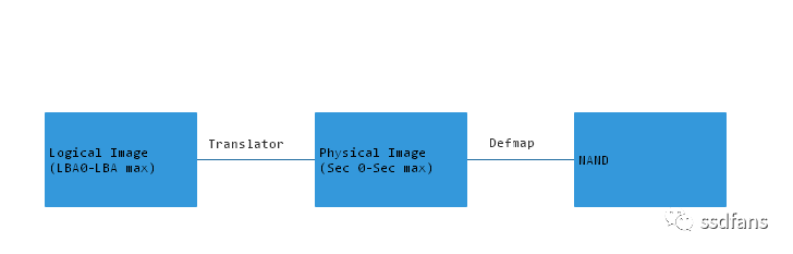
Diameter
6-160mm
Wall thickness
1-10mm