For the inverter, it is believed that many electric power practitioners are not unfamiliar. Compared with the traditional electric circuit control, the frequency converter has a high technological content and is a combination of strong and weak electricity. Therefore, its failures are various and can only be Combining theoretical knowledge with practice to sum up experience, here are 15 examples of frequently asked questions about frequency converters. Do you understand this? 1, what is the frequency resolution? has no meaning? For digitally controlled inverters, even if the frequency command is an analog signal, the output frequency is given a step. The smallest unit of this differential is called the frequency resolution. The resolution of the frequency conversion is usually 0.015~0.5Hz. For example, if the resolution is 0.5Hz, then the upper side of 23Hz can be changed to 23.5, 24.0Hz, so the action of the motor is also followed step by step. This causes problems for the use of a continuous coil control. In this case, if the resolution is about 0.015 Hz, one step for a four-stage motor is 1 r/min or less, which can be adequately accommodated. In addition, some models have different resolutions and output resolutions. 2. What is the significance of the models that can be specified for the acceleration time and deceleration time, and the type of acceleration and deceleration time given together? Acceleration and deceleration can be given for each type of machine, for short-time acceleration, slow deceleration occasions, or for small machine tools need to strictly specify the production of the tact time is appropriate, but for fan drive and other occasions, acceleration and deceleration time is longer, Acceleration time and deceleration time can be given together. 3. What is regenerative braking? When the motor is running, if the command frequency is reduced, the motor becomes an asynchronous generator state operation and operates as a brake, which is called regenerative (electrical) braking. 4. Is it possible to obtain greater braking power? The energy regenerated from the motor is stored in the filter capacitor of the inverter. Due to the relationship between the capacity of the capacitor and the withstand voltage, the regenerative braking force of the general inverter is about 10% to 20% of the rated torque. If using optional brake unit, it can reach 50%~100%. 5, inverter protection function? The protection functions can be divided into the following two categories: (1) Corrective actions are automatically performed after detection of abnormal conditions, such as overcurrent stall prevention and regenerative overvoltage stall prevention. (2) Block the power semiconductor device PWM control signal after detecting the abnormality, and make the motor stop automatically. Such as over-current cut-off, regenerative over-voltage cut-off, semiconductor cooling fan overheating and instantaneous power failure protection. 6. Why does the inverter's protection function act when the clutch is continuously loaded? When the clutch is used to connect the load, the motor rapidly changes from the no-load state to the area where the slip rate is large at the moment of connection, and the large current that flows causes the inverter to trip overcurrent and cannot operate. 7. In the same factory, the large-scale motor moves together and the inverter stops during operation. Why? When the motor starts, the starting current corresponding to the capacity will flow. The transformer on the stator side of the motor will generate a voltage drop. When the motor capacity is large, the pressure drop will also have a large effect. The inverter connected to the same transformer will make undervoltage or instantaneous stop. As a result of the judgment, the protection function (IPE) may occasionally act to stop the operation. 8. What does the stall prevention function mean? If the given acceleration time is too short, the output frequency of the inverter will change far beyond the change of the speed (electrical angle frequency). The inverter will trip due to the overcurrent and the operation will stop. This is called stalling. In order to prevent the stall from continuing to operate the motor, it is necessary to detect the magnitude of the current for frequency control. When the acceleration current is too large, the acceleration rate is appropriately slowed down. This is also true during deceleration. The combination of the two is a stall function. 9. Is there a limit to the mounting direction when installing the inverter? The structure of the inside and the back of the inverter considers the cooling effect. The relationship between the upper and the lower is also important for ventilation. Therefore, take the longitudinal position of the unit type in the tray and hung on the wall, and install it as vertically as possible. 10, inverter overvoltage Overvoltage alarms usually occur at the time of shutdown. The main reason is that the deceleration time is too short or there is a problem with the braking resistor and the brake unit. 11, the inverter temperature is too high In addition, the inverter has too high temperature fault. If the temperature alarm is too high, the temperature sensor can be checked if the temperature sensor is normal. The fault can be shielded. In addition, the fan and ventilation of the inverter should also be checked. For other types of faults, it is best to contact the manufacturer for a quick and feasible solution. 12. Overcurrent is the most frequent phenomenon of inverter alarm. Inverter over-current phenomenon (1) When restarting, it will trip at a raise speed. This is a very serious phenomenon of overcurrent. The main reasons are: load short circuit, mechanical parts stuck; inverter module damage; motor torque is too small and so on. (2) Power-on jump, this phenomenon can not be reset generally, the main reasons are: bad module, bad drive circuit, bad current detection circuit. When restarting, it does not immediately trip, but when accelerating, the main reasons are: too short acceleration time setting, too low current limit setting, and high torque compensation (V/F) setting. 13. Is it possible to use a soft start without putting the motor directly into a fixed frequency inverter? It is possible to operate at very low frequencies, but if the given frequency is high then the conditions for direct start with the commercial frequency power supply are similar. A large starting current (6 to 7 times the rated current) will flow, and the motor cannot be started because the inverter cuts off the overcurrent. 14. When the motor exceeds 60Hz, what problems should be noticed? Pay attention to the following matters when operating above 60Hz (1) Machines and devices must be fully operational at this speed (mechanical strength, noise, vibration, etc.) (2) The motor enters the constant power output range, and its output torque must be able to maintain the work (shaft, pump and other shaft output power increase in proportion to the cube speed, so speed should be paid attention to when it rises slightly). (3) The bearing life problem should be fully considered. 15. What happens if the inverter is not used for a long time? 1, the frequency converter blower bearing lubricant dry, affect the use. 2, high pressure filter capacitor is not easy to bulge for a long time, low pressure electrolytic capacitor is easy to leak.
Future Bus connectors Description
Antenk future bus connecto feature
designed in metric dirnension on 2 millimeters grid over 5 rows.
1 Standardized product through EIA (USA), IEC and CECC (international).
12 differents mating lengths on signal and 3 on power for standard connector system.
Future Bus connectors Application
Antenk offers a complete line of 5+2 and 8+2 Hard Metric Connectors as well as a complete line of 4 and 5 row Future bus Connectors.
Vertical, 5 Rows
2mm HM (hardmetric) Connector Introduction
System designed to meet the current and future needs of instrumentation applications giving excellent electrical and mechanical characteristics. It is a high performance, high density system with flexible configuration which offers upgradeability. The connector system is fully supported by Antenk spice models to guarantee choosing the right product to match the application.
ANTENK 2.0mm HARD METRIC CONNECTOR MODULES comply with international IEC 917and IEC 61076-4-101 Metric Connectors,2.0Mm Hard Metric Connectors,Hard Metric Connectors,Hard Metric Female Connector,2.0mm Future Bus Connector Male DIP,2.0mm Future Bus Connector Female DIP ShenZhen Antenk Electronics Co,Ltd , https://www.antenk.com


Future Bus connectors, which use 2mm style have a mating distance of 10mm. Both Future bus and the upgrade Future bus+ are out-dated.No additional work has been done to upgrade the specification over the years. However we still produce products which meet the Physical and Electrical layers of IEE P896.
2 Selected by IEEE as the interconnection system for Futurebus + / SCI / VicBus.
3 Multi-sources product,use for telecommunication, network, server / workstation market.
4 High tempersture materials SMT compatible.
5 Modular design giving flexibility for system design.
6 Stackable end to end without loss of contact position.
7 High density (more than 2 times as compared to the standard inch based " Euroconnector DIN 41612" ).
8 Tuning Fork female contact concept for higher robustness and improved reliability
(low contact resistance and high normal force).
9 Low insertion force design.
10 Inverse connector system (signal and power).
11 Optimized solder and compliant press-fit terminations for backplane and circuit board connectors.
Telecom backplane board

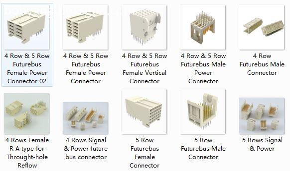
4 and 5 row Future bus Connectors
4 Rows Signal & Power
5 Rows Signal & Power
Female IDC Type 4&5 Rows
Power Connector & Cable
Shroud
Right Aangle, 5 Rows
Vertical, 4 Rows
Right Angle, 4 Rows
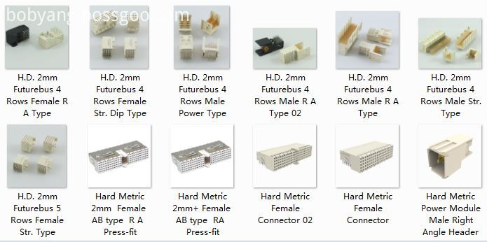
5+2 and 8+2 Hard Metric Connectors

2.0mm Future Bus Connector Male DIP
2.0mm Future Bus Connector Female DIP
2.0mm Future Bus Connector Male Press Fit
2.0mm Future Bus Connector Female Press Fit
2.0mm Future Bus Connector Power Type
standards. The connector systems in telecommunication and other industries require hight density connectors to support
larger amounts of data increasingly higher speeds antenk 2mm hardmetric modules offer the solution
Features and Benefits:
This high density connector modules can be stacked end to end without loss of space.
1,ANTENK developed the 2.0mm series under thorough consideration of impedance match, propagation delay,
cross talk, reflection. It is the ideal connector for digital high speed data application.
2,ANTENK offers differend types with inverted mating configuration. The male connector is a fixed module at the
backplane and the female commector is a free component of the plug-in module. The male connector has 5 signal row.
3 The outer shielding rows z and f of the male connector engage the shielding contacts of the famale connector. theshield
is also designed for gas tight, press-fit installation.
4 The connector system offers 15 contact length that utilize the proven press-fit assembly technique. Within the 15
contact length are 3 mating levels, achievable on both the plug-in and rear I / 0 side.
5 Coding system prevents mix-up and wrong mating between male and female connectors.
6 The 2.0mm hard metric connectors and DIN 41612 connectors can be used on the same PC board as both have the
same mating distance.
7 Staggered make-break pin populations for optional hot-swap capability.
8 Rear pin option for through-the-backplane I/O application.
9 High density PCI capability,shield for EMI/RFI protection.
2mm HM (hardmetric) Connector Features:
High density system with small real estate on backplane and daughtercard
Extensive range of signal, power, coaxial and fibre board-to-board and cable-to-board connections
Modular units give flexible configuration
Special versions for VME64 extensions and CompactPCI
Signal contact rating 1.5a fully energized
Universal power module rated at 7.8A/line, 23.4A fully energized
All lines impedance controlled to 50 (single ended) and 100Ω (differential) nominal
Safe design, complies with IEC950 in mated condition
Universal power module is safe in unmated condition
Several performance levels for board and cable connectors with unshielded and shielded versions
Mismatching keys block mating before any contact touch
Small press fit board hole allows maximum track width and minimum signal corruption
1.4 to 5.6mm (0.055 to 0.220 inch) Backplane thickness range
2mm HM (hardmetric) Connector Applications
Communications & Networking, Computers & Computer Peripherals, Sensing & Instrumentation