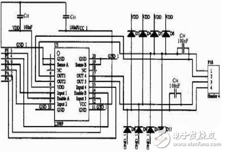
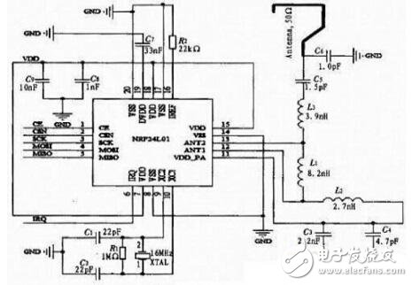
The solution is based on the Atmega128 microcontroller and wireless communication technology design. Its innovation is to control the unmanned vehicle in two ways: PC control mode and individual operation mode, which greatly enhances the functionality and environmental adaptability of the unmanned vehicle. The program can be widely used in short-distance freight passenger transportation, emergency rescue, and automatic operations in harsh environments. The intelligent unmanned vehicle is a crawler type mobile robot. Most of the unmanned vehicles on the market are controlled by single-chip microcomputers. The advantages are small size, low cost and simple structure, but it is far from relying on the single-chip microcomputer to make the unmanned vehicle Timely adjustments in complex and variable work environments and greatly limit the expansion of their functions. Based on this deficiency, the design mainly uses the wireless communication between the PC and the unmanned vehicle, so that the unmanned vehicle can perform the functions of forward, backward, turn, strike, health display, speed regulation and automatic driving under the wireless command of the PC, and Real-time access to the environment information of the unmanned vehicle through the on-board camera enables remote monitoring. In the execution of the mission, if the enemy vehicle interferes with the communication, the unmanned vehicle will identify the enemy and the enemy while resisting the interference signal, and counterattack in due course. The working principle of the unmanned vehicle system is: When the power of the teaching unmanned vehicle is turned on, the Atmega128 MCU makes the speaker send a prompt through the voice module. When the PC wireless console and PC software are ready, the PC control software sends a command to the wireless console through the USB port to configure the wireless module related registers, and the chip enters the command transmission mode; the lower computer is controlled by the Atmega128 microcontroller. After receiving the instruction of the upper computer, two PWM PWM waves and four steering control lines are generated through the integrated PWM peripheral module to increase the driving capability by the motor driving module, and then control the left and right two motors to generate corresponding actions. For example, when the PC sends a "left turn" command, the wireless module of the lower computer will automatically return to accept the success response signal after receiving the success. Then the Atmega128 MCU controls the L298P through the PA port, so that the left motor rotates in the opposite direction, and the right motor rotates in the forward direction, thus realizing the left turn function; when the PC end issues a “blow†command, the Atmega128 makes the infrared launch tube through the PE5 port. The infrared attack signal of the corresponding code system is issued; when the PC sends the "automatic driving" command, the Atmega128 combines the data collected by the receiving Hall sensor, and coordinates the motors on the left and right sides through the corresponding algorithm, so that the tank completes the straight walking and turns. Fixed angle, fixed distance and other functions. The teaching unmanned vehicle senses the attack signal of the other unmanned vehicle through an infrared sensor connected to the PE5 port. If the infrared signal is received, the PE5 port will input the fixed code system signal. At this time, the main control chip will reduce the life parameter by one and extinguish an LED light. When all the LED lights are turned off, the main control module will notify the voice chip to send out. The death warning, the drone stops all actions. Motor drive module circuit design The motor drive module is used to drive the DC motor, and the L298P motor drive chip is used. L298P is a product of SGS Company. It is a 20-pin dedicated motor driver chip. It contains two H-Bridge high-voltage, high-current dual-bridge drivers. It can receive standard TTL logic level signals and can drive 46 V, 2 A. The following stepper motors and DC motors are characterized by high voltage and high current. The circuit design is shown in Figure 3. Figure 3 Motor drive module circuit design Enable control motor stalls, connected to the PE3, PFA port of the microcontroller, the PWM wave is controlled by the two I/O ports to control the motor rotation. Input1—input4 controls the forward and reverse rotation of the motor and is connected to the PA0-PA3 port of the microcontroller. Connect two DC motors between OUT1, OUT2, OUT3, and OUT4. Wireless module circuit design The wireless module mainly includes NRF24L01 and Atmega128. The NRF24L01 adopts FSK modulation and integrates with NORDIC's own Enhanced Short Burst protocol, which can realize point-to-point or one-to-six wireless communication, wireless communication speed up to 2.4 Gbps, and configuration of its registers. Implement FM transmission. The main control chip configures the relevant registers of the NRF24L01 through the SPI protocol to complete initialization and data transmission of the wireless module. The SPI signal line of the wireless module is connected to the four I/O ports of PB0-PB3 of Atmega128, and the CE end is connected to PE2, and the integrated SPI function of Atmega128 is used for communication. The wireless module circuit design is shown in Figure 4. Figure 4 wireless module circuit design The effective transmission distance of the teaching unmanned vehicle in the wireless communication in the barrier-free area can reach 80-100 meters. The vehicle camera can be used to obtain the environmental information of the unmanned vehicle in real time and realize remote monitoring. The innovation point is that the control mode of the unmanned vehicle is controlled by the PC control mode and the individual operation mode, which greatly enhances the functionality and environmental adaptability of the unmanned vehicle. In the actual confrontation exercise, the unmanned vehicle successfully completed the functions of cargo transportation, environmental exploration, counterattacking enemy vehicles and other aspects in the event of interference, and achieved good control effects. The design can be widely used in short-distance freight passenger transportation, emergency rescue, and automatic operations in harsh environments.
The utility model relates to a medical atomization treatment and humidifying device belonging to the technical field of medical equipment and household appliances.
Professional Medical Atomization manufacturer is located in China, including Medical Vape,Dose Control Vape Pen,Supersonic Wave Vape, etc. Medical Atomization,Medical Vape,Dose Control Vape Pen,Supersonic Wave Vape Shenzhen MASON VAP Technology Co., Ltd. , https://www.e-cigarettefactory.com