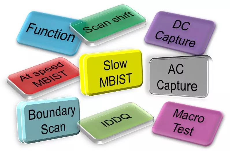
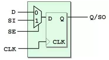
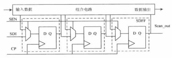
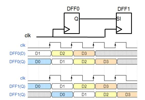
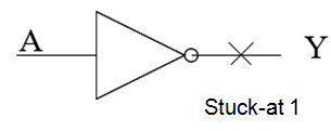
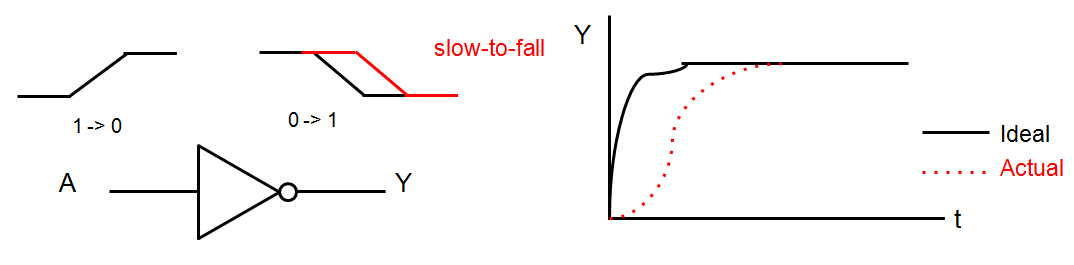
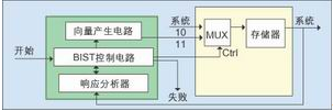
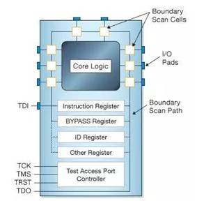
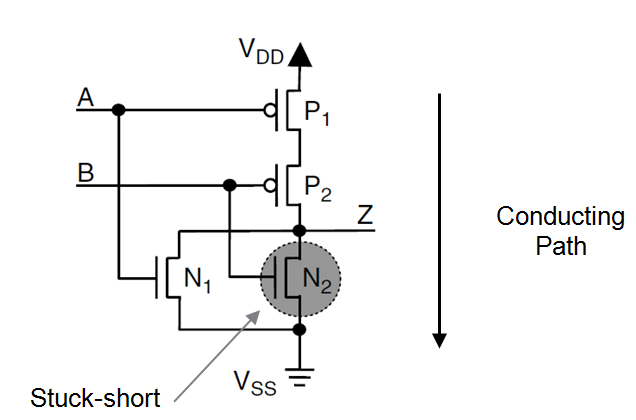
The basic concept of timing to be introduced today is Mode. This is an important concept of Sign off in the Multiple Scenario environment. The design pattern of the chip includes the most basic functional function mode, as well as a variety of related test modes. PD students should be familiar with the modes of Function, Scan Shift, Capture, and ASST. In fact, if you subdivide, these can also be divided into many new modes, as shown in the following figure. These nouns may be seen by you, but do you know that they have specific effects? Below I will briefly introduce these modes. Function This mode does not need to be introduced too much, that is, the most common functional requirement mode, that is, the standard timing constraint mode. Scan Shift This mode is also familiar to everyone, shift scan mode. First introduce the basic Scan chain concept: because the inside of the chip is a black box, it is difficult to control externally. We replace the common registers used in the chip with scan registers with scan function, which are connected end to end, so that additional test functions can be implemented. This is the concept of Scan chain. The following figure shows the scan register. The second figure below is the Scan Chain that serializes the scan registers. Therefore, when Scan enable is terminated, the scan register operates in scan shift mode, and the data pattern is shifted out. Usually, the clock frequency in this mode is very slow, generally tens of Mhz. As shown below: DC capture The capture mode is usually divided into low speed and high speed modes, corresponding to DC capture and AC capture. In Capture mode, the Scan enable signal is connected to 0, and the scan register works in normal mode. At this time, the pin connection on the function is checked. The low-speed DC capture is also the Stuck-at mode we often talk about, mainly checking our usual stuck-at 0/1 error. For example, if the inverter A terminal in the figure below is connected to the VSS terminal, it is a fault at stuck at 1. AC capture AC capture, also known as At-speed Structural Test (ASST), is a high-speed test mode that primarily tests for delay faults in the chip, which is the transition. As semiconductor manufacturing processes continue to evolve, the geometry of on-chip devices is getting smaller and smaller. At this time, due to abnormal manufacturing processes, insufficient material purity, environmental impurities and other factors, the transient time of some signals in the circuit becomes longer. If the change causes the delay on the critical path to not meet the maximum delay requirement, Then the entire circuit can't work at normal frequency. We call this failure a delayed fault. The inverter shown below, if it delays the transition time delay, will cause its entire propagation delay to exceed the ideal limit. The failure of high-performance, ultra-large-scale chips is now increasingly manifested as delay failures rather than traditional stuck-at failures. Therefore, this ASST mode is also very important, and is usually defined as a mode in the mcmm environment. At Speed ​​MBIST MBIST is also divided into high speed and slow speed, but it is generally tested at high speed, and slow speed is rarely used. In high speed mode, the memory read and write function is generally tested. MBIST, full name Memory Built-In Self-Test. MBIST is a test method for embedded chip memory to test whether the memory works normally. Inside the chip is a BIST Controller that generates the various modes and expected results of the memory test and compares the read and expected results of the memory. Why do you need MBIST? When the scan chain is long and the number is large, the single-chip test time is very long, and the price of advanced test instruments is also rising rapidly, so BIST technology came into being. The advantages of using BIST technology are: reducing test costs, improving error coverage, reducing test time, facilitating customer service and independent testing. MBIST mode is generally overridden under function mode Slow MBIST Low-speed Mbist, which is generally not needed, is only used for debugging, or for some high-speed measurements. Boundary Scan Boundary Scan, we call it boundary scan. It is a joint research and action group (JTAG), an organization jointly established by some large companies in Europe and America, mainly to solve the interconnection test between chip and chip on PCB. Boundary scan is to add a memory cell to each input and output pin of the chip, and then connect these memory cells into a scan path to form a scan chain. Since this scan chain is distributed at the edge of the chip, it is called Boundary Scan. In short, this mode mainly tests the signal on the chip IO, which is generally included under the function mode. Macro Test In this mode, mainly test some Analog modules and some other IP. IDDQ IDDQ full name Integrated Circuit Quiescent Current, which is a quiescent supply current, which is a mode that mainly detects leakage of the device. The purpose of the IDDQ test is to measure the static (steady) current during logic state verification and compare it to the standard quiescent current to improve test coverage. The IDDQ test runs a sequence of functional static IDD tests, with 6 to 12 independent current measurements at individual breakpoints within the functional sequence. The goal of the test sequence is to switch the internal logic gates on as much as possible while verifying the total IDD current at each breakpoint, with the toggle rate as high as possible. The IDDQ test can directly detect whether there are small damages in the device circuit core that cannot be detected by other methods. Ok, the introduction of Mode is here. Our usual mcmm file will not be so fine, most Mode will be merged, generally the last remaining only function, scan shift, asst and other major modes, the other can be switched by setting the case value. Nanning Ousibang Information Technology Co., Ltd. , https://www.ousibangvape.com