Digital multimeters are very important for engineers in the electronics industry. They are easy to operate, accurate in data, and can quickly determine real parameters such as current, capacitance, and diode. Many methods used in digital multimeters have incorrect operation. In this article, the author teaches you the correctness of digital multimeters. Instructions. Start with the standard multi-function measurement methods such as voltage, resistance, current, and diodes of the digital multimeter, so that you can better master the digital multimeter measurement method.
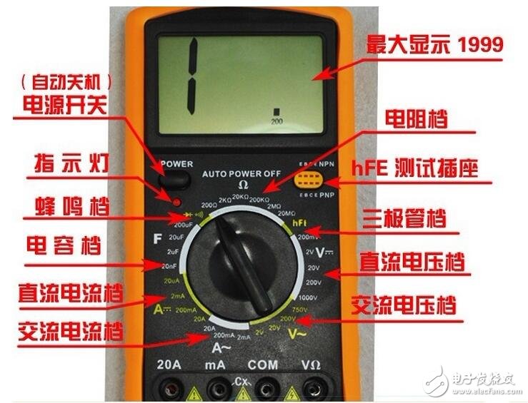
First, let's talk about the digital multimeter operating procedures and precautions.
Method of using digital multimeter and method of testing current, capacitance and diode----Operation procedure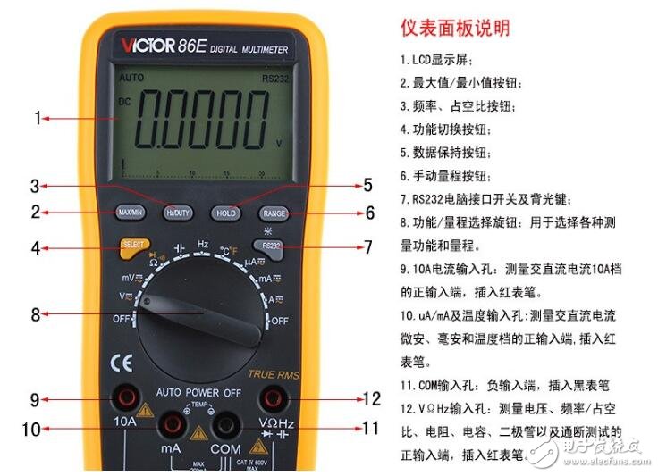
1. Be familiar with the functions of the digital multimeter before use. According to the object to be measured, select the gear position, range and pen jack.
2. When the size of the measured data is unknown, the range switch should be set to the maximum value, and then switched from the large range to the small range, so that the meter pointer can be indicated at 1/2 or more of the full scale.
3. When measuring the resistance, after selecting the appropriate magnification file, touch the two test leads to make the pointer point to zero. If the pointer deviates from the zero position, adjust the “zero adjustment†knob to zero the pointer to ensure accurate measurement results. . If you can't zero or the digital display sends a low voltage alarm, you should check it in time.
4. When measuring the resistance of a certain circuit, the power of the circuit under test must be cut off.
5. When using a digital multimeter for measurement, pay attention to the safety of the personal and instrumentation equipment. Do not touch the metal part of the test pen by hand during the test. Do not switch the gear switch with power to ensure accurate measurement, avoid electric shock and burn the instrument. ACCIDENT.
Method of using digital multimeter and method of testing current, capacitance and diode----Notes on the use of digital multimeter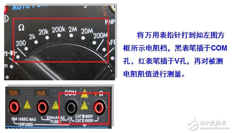
(1) Before using the digital multimeter, perform “mechanical zeroingâ€, that is, when there is no measured power, the digital multimeter pointer points to the zero voltage or zero current position.
(2) In the process of using the digital multimeter, the metal part of the test pen cannot be touched by hand, so that the measurement can be ensured on the one hand, and the personal safety can be ensured on the other hand.
(3) When measuring a certain amount of electricity, it is not possible to shift gears while measuring, especially when measuring high voltage or large current. Otherwise, the digital multimeter will be destroyed. If you need to change gears, you should first disconnect the test leads and then change the gears before measuring.
(4) When using the digital multimeter, it must be placed horizontally to avoid errors. At the same time, we must also pay attention to avoiding the influence of external magnetic fields on the digital multimeter.
(5) After the digital multimeter is used, the switch should be placed at the maximum limit of the AC voltage. If it is not used for a long time, the battery inside the digital multimeter should be taken out to prevent the battery from corroding other devices in the watch.
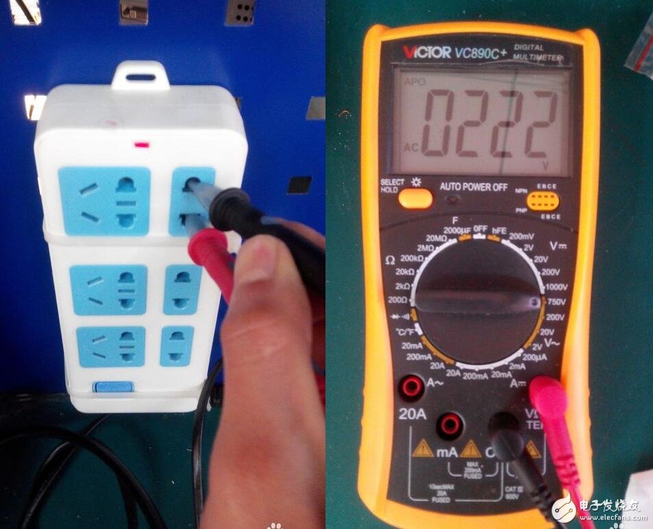
Digital multimeter usage method and method for testing current, capacitance and diode----Digital multimeter test voltageFirst of all, we will open the digital multimeter. We are testing our China's mains, AC220V, but if we are not clear about the test voltage, we should hit the most range to AC750V, ~ wave shape represents AC voltage, rotation Do not select the wrong time for the turntable.
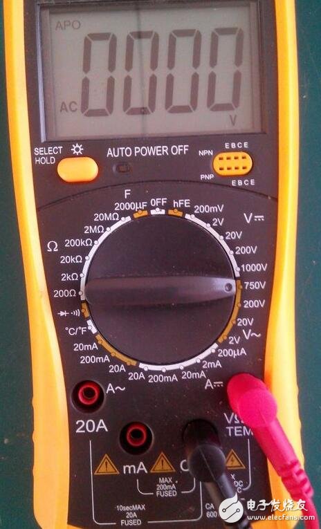
Now we insert the red test lead and the black test lead into the discharge socket. Then we observe the digital change on the digital multimeter. The measured voltage is AC222V, because the alternating current is changing, but this voltage is normal within the variation range.
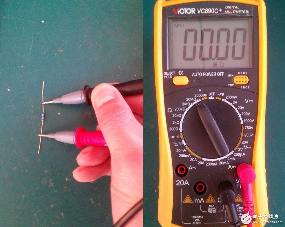
Next, let's test the resistance of the resistor. First, we turn the turntable to the maximum position of the resistor file by 20M, because we can maximize the range without knowing the resistance value.
Then connect the red test lead and the black test lead to the two ends of the resistor for testing. At this time, the digital multimeter displays the resistance value as 0. At this time, we will reduce the turntable in turn until the correct resistance value is displayed.
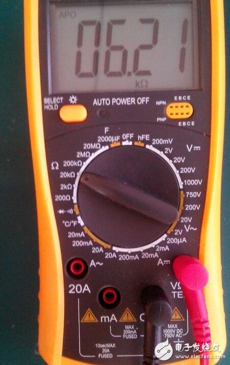
By adjusting the range of the turntable, we tested the resistance at 6.10K at the 10K position. Now we have tested.
Select range: Digital multimeter DC current file has "mA" with 1mA, 1omA, 100mA three-range range. The range selected should be based on the current in the circuit.
1, select the range: digital multimeter DC current file with "mA" has 1mA, 1omA, 100mA three-range range. The range selected should be based on the current in the circuit. If you do not know the current size, you should use the maximum range.
2. Measurement method: The digital multimeter should be connected in series with the circuit under test. After disconnecting the corresponding part of the circuit, connect the digital multimeter to the ends of the breakpoint. The red test pen should be connected to the breakpoint connected to the positive pole of the power supply, and the black test lead should be connected to the breakpoint connected to the negative pole of the power supply.
(1) Connect the circuit to make the LED emit light normally.
(2) Prepare the digital multimeter and place the selector switch in the mA range of 100 mA as described above.
(3) Disconnect the lead between the indirect point of the potentiometer and the negative terminal of the LED to form a “breakpointâ€. At this time, the LED is turned off.
(4) Connect the digital multimeter in series at the breakpoint. The red pen is connected to the negative pole of the LED, and the black pen is connected to the indirect lead of the potentiometer. At this time, the LED re-illuminates. The scale value indicated by the DMM pointer is the current value through the LED.
(5) Correctly read out the current value through the LED. Record: The current through the LED is xx mA.
(6) Rotate the potentiometer knob to observe the change of the digital multimeter pointer and the brightness change of the LED. Record: The maximum current through the LED is xx mA. The minimum current is xx mA. Through the above operations, we can further understand the role of the resistor in the circuit.
(7) After the measurement is completed, disconnect the power supply and collect the digital multimeter as required.
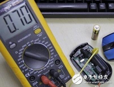
Using the digital multimeter diode file, insert the red test pen into the VΩ hole and insert the black test lead into the COM hole. We know that in the digital multimeter, the red test pen touches the internal battery positive pole, the black test pen touches the internal battery negative pole, and the pointer in the pointer multimeter is the red test lead contact inside. The battery negative black pen touches the internal battery positive pole, the digital multimeter red pen touches the diode positive pole, the black test pen contacts the diode negative pole, (measures the forward resistance value), the normal value is 300-600Ω
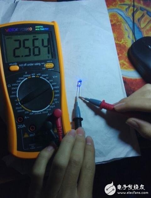
Then, touch the red test lead to the negative pole of the diode, and the black test lead to the positive pole of the diode (measuring the reverse resistance value). The normal value is “1â€. If both measurements show 001 or 000 and the buzzer sounds, the diode has broken down. The two measurements of the forward and reverse resistance values ​​are all "1" indicating that the diode is open. If the two measured values ​​are close, the tube quality is very poor. The reverse resistance value must be "1" or more, and the forward resistance value must be 300. -600Ω. Then the diode is good.
xcool vape enjoy free, Disposable Vape Pen brand
Xcool vapor disposable vape pen, xcool vapor hnb, xcool vapor cbd
Shenzhen Xcool Vapor Technology Co.,Ltd , http://www.xcoolvapor.com