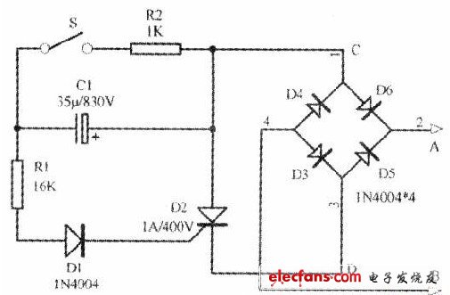
As shown in the figure below, it is an automatic delay lighting switch circuit. This circuit has certain practicability. When the light is turned off at night when the room is turned off, if the switch of the light is not at the door, then it will be black to the door after turning off the light. Convenience. However, if you use the circuit shown below, you can delay the time after turning off the lights, so that you have enough time to leave the room and avoid the black. In the circuit, A and B are respectively connected to the two ends of the original switch. When the switch S in the circuit is closed, the positive half cycle of the alternating current is applied to the thyristor control pole via D6, R2, R1 and D1, triggering the thyristor conduction: alternating current The negative half cycle D4, R2, R1, D1 are also applied to the control electrode of the thyristor, triggering the thyristor conduction. After the thyristor is turned on, it is equivalent to short-circuiting C and D, so that the two points A and B are also closed by the diode and the conductive thyristor. At this time, the lamp housing is illuminated. After the switch S is turned off, since the capacitor C1 is discharged through the thyristor control electrode, R1 and D1, the thyristor still has a trigger current to maintain conduction. As the discharge current gradually decreases, after a while, the thyristor is turned off, and the illumination lamp is extinguished. According to the parameter values ​​shown in the figure, the circuit delay time is about 40~50 seconds. Component selection: The thyristor can select the working current as 1A and the withstand voltage to be 400V; D1, D3~D6 can use the rectifier diode of lN4004. Cl uses an electrolytic capacitor with a withstand voltage of 630V and a capacity of 35μF. Note: After the circuit is properly assembled, if the S switch is closed and the light does not illuminate, the resistance of R1 can be appropriately reduced.
Power 30W ,output voltage 3-12V, output current Max 1.2A , USB output 5v 2a, 6 dc tips. We can meet your specific requirement of the products, like label design. The material of this product is PC+ABS. All condition of our product is 100% brand new.
Our products built with input/output overvoltage protection, input/output overcurrent protection, over temperature protection, over power protection and short circuit protection. You can send more details of this product, so that we can offer best service to you!
30W Wall Adapter ,30W Wall Power Supply,30W Power Cord In Wall, 30W Wall Power Adapter Shenzhen Waweis Technology Co., Ltd. , https://www.szwaweischarger.com