The most difficult thing to repair a professional amplifier is the lack of drawings and materials. For ease of maintenance. For the professional amplifiers that have been repaired, the schematic diagrams are actually measured, and the willingness is dedicated to the maintenance workers. The QSA-1600 professional power amplifier circuit structure is divided into 4 large blocks: power supply; signal input mode selection, stereo and bridge selection; power amplifier circuit; speaker protection circuit. The OSA-1600 power amplifier is a switching power supply. Its power supply voltage is ±80V.±24V.+12V, a set of switching power supply for each channel, the principle is shown in Figure 1. The working principle is as follows: power-on rectification +300v voltage is applied to the thick film block (no model) (1) foot, and the thick film block starts to oscillate from (3). (4) The foot conveys the switch pulse to the B2 transformer (3), (4) winding. B2 (7), (8) winding induced voltage makes Q2 conduct. The Q1 and Q2 currents pass through the windings of the switching transformers B1(2) and (3). B3 5, 6 winding negative reverse winding to feed the feedback voltage into the thick film block (7), (8) foot. B1 (4), (5) windings are operating voltage adjustment detection windings, the main fault is thick film block and high power tube damage. There are no models for thick film blocks. Can only be purchased through a dealer. If the high-power tube is replaced by 1500V or 10A triode, if the thick film block is damaged, the rectifier tube and ±80v filter capacitor should also be detected. There are two types of QSA-1600 signal input methods: balanced and unbalanced. The balanced input mode signal is not amplified by the NE5534. Directly into the upper end of the volume potentiometer. Unbalanced input R and L channel signals are amplified by NE5534. Then go to the top of the potentiometer. This unit also has stereo and bridge switchers. In the stereo position, the R and L channels are amplified by the NE5534 and then advanced into the volume potentiometer. The R channel signal is not used when bridging. l. The channel signal is amplified into the L channel volume potentiometer via the NE5534 in an unbalanced state. The R channel input signal is slid from the L channel volume potentiometer to extract the audio signal through the R5 to NE553 (2) pin inverting input. (6) The pin is inverted to the upper end of the R channel volume potentiometer. When the bridge is connected, the input and output signals of the R and L channels are opposite in polarity. The speaker is connected to the positive terminal of R and L, and the positive terminal is connected to the red terminal of the L channel. The negative terminal is connected to the R channel red terminal. The main fault in this part is the poor contact of the input mode switch and the damage of the operational amplifier NE5534. NE5534 feet function shown in KNLE1-63 Residual Current Circuit Breaker With Over Load Protection
KNLE1-63 TWO FUNCTION : MCB AND RCCB FUNCTIONS
leakage breaker is suitable for the leakage protection of the line of AC 50/60Hz, rated voltage single phase 240V, rated current up to 63A. When there is human electricity shock or if the leakage current of the line exceeds the prescribed value, it will automatically cut off the power within 0.1s to protect human safety and prevent the accident due to the current leakage.
KNLE1-63 Residual Current Circuit Breaker,Residual Current Circuit Breaker with Over Load Protection 1p,Residual Current Circuit Breaker with Over Load Protection 2p Wenzhou Korlen Electric Appliances Co., Ltd. , https://www.zjmoldedcasecircuitbreaker.com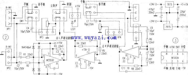
leakage breaker can protect against overload and short-circuit. It can be used to protect the line from being overloaded and short-circuited as wellas infrequent changeover of the line in normal situation. It complies with standard of IEC/EN61009-1 and GB16917.1.