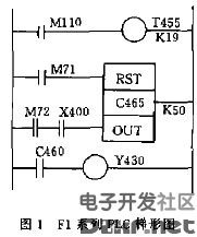
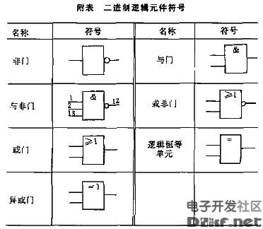
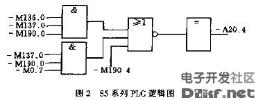
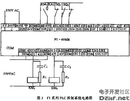
Programmable controller electrical wiring diagram 1 Introduction Programmable controllers have maintained annual sales growth rates of more than 25% since the introduction of Cambodia in the 1960s, and are moving toward high functionality, high speed, large capacity, and networking, and programming languages ​​are becoming more and more advanced. In order to adapt to its development, the International Electrotechnical Commission IEC has revised the programmable controller standard several times. International Electrotechnical Commission IEC1131 shrinkable program controller standard mainly defines the definition of the shrinkable controller, vocabulary, PLC hardware structure, use environment, electrical requirements, mechanical requirements, materials necessary for the manufacturing company, testing and verification methods, programming language , user guides and information communication and other aspects have been stipulated. There are no provisions for the electrical graphic symbols of the programmable controller. The International Electrotechnical Commission's IEC 617 "Graphical Symbols for Electrical Sketches" standard does not specify the electrical graphic symbols of programmable logic controllers. China's corresponding national standard GBiT4728 "graphic symbols for electrical schematics" is also not mentioned. The application system of programmable controller is more and more. This paper discusses how to apply the existing national standard to draw the electrical drawings of the programmable controller. Second, programmable controller control system electrical diagram type The types of electrical diagrams of the programmable controller control system mainly include schematic diagrams, sequence diagrams, timing diagrams, program diagrams, circuit diagrams, wiring diagrams, and the like. The diagrams represent a relatively simple diagram of the main relationships and connections between systems in systems, subsystems, devices, components, devices, and software. The order table diagram shows the working order or state of each unit of the system. The work or state of each unit is arranged in one direction, and the process steps or time are drawn at right angles on the figure. The sequential bezel is the most widely used in programmable step sequence control, such as machining automatic lines. The timing diagram is a sequence diagram program that plots the timeline in proportion. It is a simplified diagram that details the program units, modules, and their interconnections. A circuit diagram is a simplified diagram showing actual circuits of a system, subsystems, components, devices, software, etc., and graphical symbols arranged by functions are used to represent components and connections. A wiring diagram is a diagram that represents or lists the connection relationships of a device or device. Third, the drawing of the common electrical diagram of the programmable controller control system 1. Program circle drawing According to the International Electrotechnical Commission IEC1131 shrinkable program controller standard: programmable language programming language can use textual language and graphical language. Textual languages ​​refer to boasted list and structured text, while graphical languages ​​have trapezoidal and flow charts. For text-based programming languages, there are specific regulations for each PLC manufacturer. There is no need to say more here, but graphical languages ​​have their own characteristics and must be noticed when drawing. (1) Ladder drawing Ladder diagram is a special limitation language of programmable controller. It still uses relay symbols in relay logic control, such as normally open contacts, common contacts, coils, etc. The arrangement method is similar to the relay control circuit diagram. Manufacturers, instruction mnemonics are not the same, but the graphic symbols of the relay are the same, such as the symbol of the normally open contact, the symbol of the normally closed contact {the symbol of the coil - 0. The relay in the programmable controller" is Visualized terminology for programming, which is represented by the state of the corresponding bit in the memory. It is not an actual electrical component. There is no such graphic symbol in the national standard. For example, the ladder diagram is drawn by PROTEL98, and there is no such thing in the PROTEL component library. Symbol. Must be separately built library. In addition, for complex arithmetic operations, timing counting. PID regulator and other functions. Generally represented by a block diagram, with different symbols, leaving the input parameter port. Figure 1 is a time count, etc. Functional Mitsubishi Fl series ladder diagram. (2) Flow chart drawing The PLC control flow chart generally adopts a logic diagram logic diagram, that is, a logic function diagram, which is a function diagram mainly using binary logic component symbols. Using logic diagram programming, the logic relationship is very clear. It is mainly used in large and medium-sized PLCs. For example, in Siemens s5 series PLC, this programming language logic diagram is used to represent the logical relationship between the various quantities in the program, which is software implementation. Method, there is no actual two-in-one logic component, but in the logic diagram design, we use the logical symbol in the national standard GB/T4728 12 1996 "Electrical diagram with graphical symbol binary symbol", as shown in the attached table: Use PROTEL98 to draw the logic diagram. If the circuit diagram component library uses the national standard symbol, the symbol in the library can be directly called. If it does not match the national standard, it must be built according to the national standard. In addition, when drawing the logic diagram, it must conform to the national standard GB/T6988-1997 "Compilation of documents for electrical technology". Figure 2 is the logic diagram of Siemens s5 series PLC. 2. Circuit diagram drawing The programmable controller control system circuit diagram usually includes the input and output parts and the PLC itself. The input section usually refers to various types of buttons or switches and various switch information on the controlled object, such as limit switches and photocell signals. The output part is an electric appliance including various electromagnetic coils, various contactors for turning on the motor, signal indicators, etc. For the above electrical components, the national standard specifies their graphic symbols, and the national standard symbol must be selected when drawing the circuit. The national standard for graphical symbols of programmable controllers is not specified. Therefore, we must design the graphical symbols of the programmable controller according to the design rules of the graphic symbols when drawing the circuit diagram. The design principles of electrical graphic symbols are: 1 The content of graphic symbols is function, specific information. 2 The configuration of graphic symbols should be simple, easy to understand, easy to reproduce, easy to associate with meaning, and easy to remember. 3 The meaning of graphical symbols should be able to be recognized by the content before and after, if not, additional information should be provided. @ Graphics symbol line width to modulus ratio is 1:10, when the line width is different, the two line width ratio should be 1:2. The terminals of the line should be placed at the point of the network. 5 The minimum spacing of parallel lines should be at least 2 times the width of the widest line. When writing text between parallel lines, the distance between lines should be at least 2m. 6 Text description: The font is in accordance with the national standard B type straight body. The writing direction of the text is written horizontally and vertically. When text is part of a graphic symbol, the text is placed first or middle. The input and output text is placed in the position of input and output. The distance between the text and the symbol is not less than twice the width of the thickest line. 7 There is no special requirement for the graphic symbol size. According to the above design rules and the distribution of the output terminal of the PLC, the shape of the PLC symbol is designed to be rectangular, the input terminal is placed at the upper part, the output terminal is placed at the lower part, and the text number of the output terminal is marked at the corresponding position. Considering that the input and output numbers of PLCs of different manufacturers are different, the above design symbols cannot be used as general symbols of PLC. PLCs of different manufacturers should independently design graphic symbols according to the above principles. Figure 3 shows Mitsubishi Fl-40MR programmable controller. Control circuit diagram of the system. 3. Connect the coil to draw National Standard GB/T6988.3—1997 “Editing Wiring Diagram and Wiring Table for Documents for Electrical Technology†stipulates that the components in the wiring diagram should be represented by a simple outline such as a square, a rectangle or a circle, or a simplified graphic representation. Using the graphical symbols specified in GB4728, the terminals should be clearly indicated, but the terminal symbols need not be shown. To this end, when we draw the wiring diagram of the PLC control system, the representation of the PLC component directly uses the graphical symbols in the circuit diagram, and the other drawing rules are the same as the general electrical control system. It is also worth noting that when the programmable controllers use more modules or units, they must consider their actual placement. The units can be placed horizontally or vertically. When the unit is placed horizontally, do not pass the cable slot or the distribution line between the CPU unit and the I/O unit. Flashlight Battery,Car Lithium Battery,Battery For Flashlight,3V Flashlight Battery Jiangmen Hongli Energy Co.ltd , https://www.honglienergy.com


