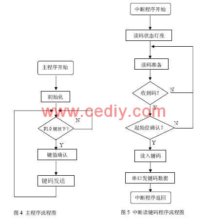
At present, the projector is already a conventional device of a multimedia classroom in a university, but due to frequent use and complicated personnel, the damage and loss of the projector remote controller sometimes occurs. Because the projectors used in schools are imported products, the remote control is difficult to match, and the price is extremely expensive when it can be bought. Using the function of the single-chip simulation remote control, the projector remote control with low cost is practical and popular. This article refers to the address: http:// 1.2 Reading the remote control key code software design Figure 4 is the main program flow of reading the remote control key code control software. Figure 5 is a flow chart showing the procedure for interrupting the reading of key code data. Interrupting the reading of key codes is very important in programming. It needs to complete the identification of the start bit of the remote control code and the pulse width count, the width count of the remote code coded bit, and the recognition of the end bit. Through a large number of different types of remote control code waveform analysis, the frame interval width of the remote control code is more than 10 ms, the starting bit code width is between 100μs and 20ms, and the coding bit is between 100μs and 5ms, to ensure that all The success of remote control reading is based on the following design methods: Ningbo Autrends International Trade Co.,Ltd. , https://www.mosvapor.com
The key to making the projector remote control is to read the control code data of all the buttons of the original projector remote control (same model), and then make the button control code table. When the simulation is performed, the MCU will have different control codes under the button operation. The data is transmitted out to achieve the purpose of remotely controlling the projector.
1 Read the remote control key code method
1.1 Reading the remote control key code hardware circuit Figure 1 is the control circuit of the single-chip read projector remote control key code. The single-chip microcomputer uses the STC12C5410 of Hongjing Company, the P1.6 port light is used as the indication of the reading status, and the light is on behalf of the reading status. P1.7 port light is used to indicate the remote control transmitting operation. When flashing, it means the remote control code is transmitted. In the reading state, when the P1.6 port light is off and the P1.7 port light is on, the representative code has been read. The first (1) pin is the reset pin of the MCU, and the simple RC power-on reset circuit is used. The (6) pin is the external interrupt input port, which is used for the conversion control of the reading function. When the (6) foot switch is pressed, The system enters the interrupt reading state. (8) The foot is used for reading the output signal of the infrared receiving head. (11) The foot acts as an infrared signal output port of the remote controller for outputting 40KHz carrier code. (12) The foot is connected to the remote control test switch. (4), (5) external 12M crystal oscillator. 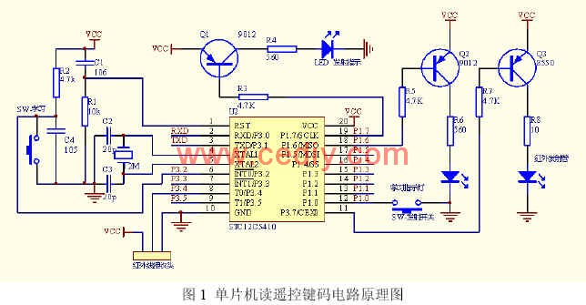
When the “learning†switch is pressed, the reading light of the P1.6 port lights up, indicating that the reading state is entered. At this time, a button of the remote controller that needs to be simulated is pressed against the infrared receiving head, and the light of the P1.6 port is extinguished. When the indicator of the P1.7 port is on, the reading is successful. The key code data can be obtained from the serial port of the computer HyperTerminal. In order to test whether the code read is correct, you can press the launch test switch to see if the projector's functional operation can be correctly implemented. According to the above method, all the key codes of the original projector remote controller are read into the computer for backup. Fig. 2 and Fig. 3 are waveform diagrams of the output port of the single chip when the output port of the infrared receiving head and the remote control code are transmitted, respectively. 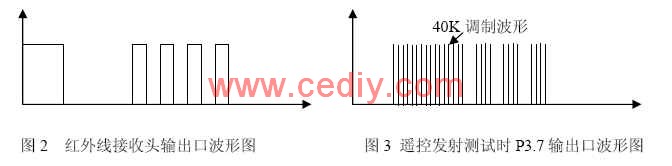
(1) Finding the start bit method: Use the 16-bit DPTR counter to count the high level, and the count sampling period is 21μs. When the high level ends, if the high 8-bit counter is non-zero, the high level is wide. More than 5.35ms (255 × 21μs), the next low level code is the start bit, otherwise it starts again.
(2) Read start bit method: 16-bit DPTR is used to count the low level (maximum readable width is 1.376s), when the high level jumps, the end is counted, and the high and low bits of DPTR are 8 Store in the R4, R5 registers respectively.
(3) Method of reading remote control code: use DPTR low 8-bit counter to count the width of code (high level or low level), end counting when level jumps, and store the value in the specified address, at high power In the case of flat code counting, if the DPTR high 8-bit counter is non-zero (width greater than 5.35 ms), it is determined that the frame interval bit is ended, and OOH is written as an end flag in the corresponding memory cell.
2 Projector simulation remote control design
2.1 Simulation remote control hardware circuit design Figure 6 is the circuit schematic of the projector simulation remote control. With 4*8 determinant button switches, there are 32 operating buttons. The remote control outputs a 40K infrared modulation signal from the P3.7 port. 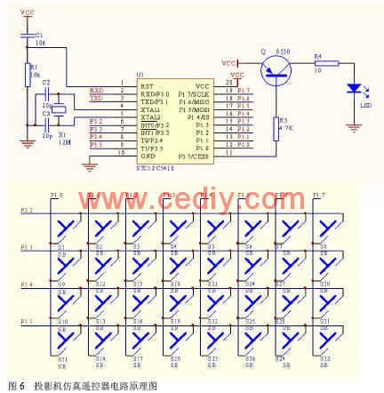
2.2 Simulation remote control software design In the simulation remote control, the corresponding key code transmission function is executed by the loop check key of the main program. The key code table is written in the ROM, so it cannot be changed after programming. The program includes the following main modules:
(1) Initialization procedure. The P1 and P3 ports are set, and the counter counting mode, control word, etc. are set.
(2) Keyboard scanning program. The 32 keystrokes are completed and translated into the corresponding 32 key numbers to enable the corresponding key functions.
(3) Key function program. The timer timing interrupt function is used to realize the generation of the 40KHz carrier; the corresponding start bit control data, the high level control data, and the low level control data of each button on the ROM table are used to control the transmission time and interval time of the carrier. The algorithm for remote code modulation transmission is as follows:
1[starting start modulation wave]
Take the start bit data in the ROM table;
Open 40KHZ square wave timer;
The start bit data is decremented by 1, not zero, and the sentence is repeated after a delay of 21 μs;
Execute the next sentence at zero;
2[high level interval]
Off 40KHZ square wave timer;
Take the high level data in the ROM table; if the data is 0, the algorithm ends after a delay of 10ms; the next sentence is executed without zero;
The data is decremented by 1, not zero, and the sentence is repeated after a delay of 21 μs;
Execute the next sentence at zero;
3[low level modulation wave]
Take low level data in the ROM table;
Open 40KHZ square wave timer;
The low level data is decremented by 1, not zero, and the sentence is repeated after a delay of 21 μs; zero to 2 cycles;
4 algorithm ends
3 Main performance indicators (1) The maximum learning code length of the reader: 206bit
(2) Read range of code reader reading: start bit: 21μs~1.376s, coding bit: 21μs ~ 5.355ms
(3) Reading error: +21μs
(4) Interrogator frame intermittent bit recognition range: less than 1.37s, greater than 5.355ms
(5) Simulation remote control launch distance: greater than 10M
4 Summary of the multimedia projector's MCU simulation remote control performance and software design has a close relationship, especially the sampling period of the code width count, is related to the ability to identify the starting bit and remote control code sampling accuracy problems, in programming more The second experimental test, taking into account each other, the sampling period of the code reading in this design is 21μs, which can be used to correctly simulate the projectors, color TVs, air conditioners and other equipment commonly used in the market.