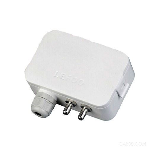
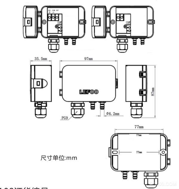
The gas differential pressure sensor is a product based on the mechanical differential pressure table and the mechanical differential pressure function. The product is mainly composed of three parts: gas pressure change sensing system, signal collection and conversion unit, and data output unit. The sensing of pressure changes is measured and converted into analog or digital signals for transmission to the acquisition control system. The purpose of gas flow control is achieved by detecting changes in the gas micro-pressure. Generally used in a large number of areas such as HVAC systems, energy management systems, VAV and fan control, environmental pollution control static piping and clean room pressure, smoke hood control, oven pressurization, and furnace ventilation control. The gas differential pressure sensor is based on the mechanical differential pressure meter and the mechanical differential pressure function. The mechanical pointer differential pressure meter only has the pointer display function, and the mechanical pressure differential meter can only realize the gas pressure in the invisible environment. Change alarm or approximate control, mechanical products have measurement roughness and mechanical transmission characteristics, and gas micro-differential sensors are electronic chip control sensing core unit to achieve digital visualization, high-precision measurement, big data processing and other characteristics to meet the modern intelligent centralized control System signal acquisition requirements. The product mainly consists of three parts: the gas pressure change sensing system, the signal collection and conversion unit, and the data output unit. It measures the change in gas pressure and converts it into an analog or digital signal for transmission to the collection control system. To achieve the purpose of gas flow control. Sensing system is generally chip sensing, conventional diffusion silicon crystals and other chips, the superiority of its product performance for the quality of the chip determines the core performance, through the sensing system to collect gas pressure after the original data through the processing chip to achieve analog or digital signal output, Complete the data repair in different environments. The general output method is the output source of micro-signal (V) (mA), which is transmitted to the centralized control system through the beamline or optical fiber, and finally realizes the collection of gas pressure at the site and the control system. Complete the appropriate program for distribution. At present, the main products in the market are: non-programmable differential pressure sensor, programmable differential pressure sensor, programmable differential pressure sensor with display Generally used in a large number of areas such as HVAC systems, energy management systems, VAV and fan control, environmental pollution control static piping and clean room pressure, smoke hood control, oven pressurization, and furnace ventilation control. Basic features Response time: 0.5s, 1s, 2s, 4s Resolution: LFM110/1Pa, 0.1mmH O, 0.01mbar, 0.004inWG, LFM112/0.007mmHG, 0.1daPa, 0.001KPa, 0.001hPa LFM116 / 0.1Pa, 0.01mmH O, 0.01mbar, 0.01daPa, 0.001hPa Zero calibration: manual key zero calibration Measuring medium: air and neutral gas Allow overvoltage: 15KPa(LFM110); 150KPa(LFM112); 4.5KPa(LFM116) Working temperature: -10~+60°C Storage temperature: -10~+70°C The main function The differential pressure sensor/transmitter detects differential pressure or gauge pressure and converts this pressure value into a proportional electrical signal output for intelligent building energy The management system serves to measure the precise pressure and flow required for building pressurization and air flow control. The pressure value can be set in the field through the built-in dial switch of the LFM11 series. l Range: 0 ~ ±10Pa/0 ~ ±10,000Pal Accuracy: ±1.0%l A variety of pressure units can be switched LCD backlight digital display or no display l Boot automatic zero calibration The response time is adjustable through the built-in DIP switch (0.5S ~ 4S) Manual pressure differential zero calibration Imported micro pressure core l The rotation method is fixed to the installation backplane (the installation board is separated from the host so that step-by-step installation can be performed) Installation method Mark the mounting holes on the wall with the back scale, and place the expansion tube (with self-tapping screws and expansion tube) on the 6mm wall hole with 30mm depth. Differential pressure sensor installation Then open the differential pressure transmitter buckle, open the cover, and fix the self-tapping screw (ST3.5×25) to the designated seat on the wall through the fixing hole of the differential pressure transmitter and connect it through the waterproof joint. Wire, and finally cover it. Specifications LFM110 -1,000 ~ +1,000Pa minimum 0 ~ +100Pa LFM112 -10,000 ~ +10,000Pa Min. setting 0 ~ +1000Pa LFM116 -100 ~ +100Pa Minimum can be set to 0 ~ +10Pa Accuracy ±1.0% Pressure unit: Pa, mmH2O, mbar, inWC, mmHG, daPa, KPa, hPa output signal: 0~5VDC, 0~10VDC, 4~20mA, RS-485 signal (Two-wire, three-wire output can use analog signals at the same time; RS-485 type only has RS-485 signal output) power supply: 1ã€Two groups output at the same time, the input voltage is 16~30VAC/VDC, can be equipped with 24VDC adapter (3.5x1.35mm) power supply 2, 4 ~ 20mA (two-wire system) output, the input voltage is non-polar 12 ~ 30VDC 3, 0~5V/10VDC output, input voltage 16~30VAC/VDC 4, RS-485 output, input voltage is 12~30VAC/VDC Power consumption: ≤1.5W Remarks: No polarity: input voltage source is not divided into positive and negative Mechanical parameters Shell material: Industrial plastic, protection class IP54 Display: Backlit LCD display, 50 x 22.5 mm (two-wire without backlight) Digital height: measured value 10 mm, unit 5 mm Pressure Interface: Metal Barb Interface, ? 6.2 mm Cable connector: maximum cable diameter 8 mm Weight: 166g Medical IT Isolated Power System
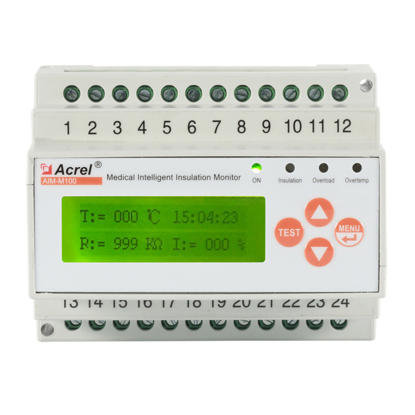
The medical Hospital Isolated Power Supply System is mainly used in important Class 2 medical locations such as operating rooms, ICU/CCU intensive care unit, providing safe, reliable and continuous power distribution for the important equipment at these locations. Medical IT system insulation monitoring and fault locating products (five-piece set) include AITR series medical isolation transformer, AIM-M100 insulation monitoring devices, AKH-0.66P26 Current Transformer, ACLP10-24 DC power supply, and AID series(AID100, AID120, AID130, AID150) centralized alarm and display instrument.
Isolation Power Cabinet,Insulation Fault Locator,Medical Isolation Transformer,Medical Intelligent Insulation Monitor Jiangsu Acrel Electrical Manufacturing Co., LTD. , https://www.acrel.com.pk
 l
l 
The Intelligent Realization of Gas Flow Control in Micro-pressure Differential Transmitter
Acrel Electric Co., Ltd. [Stock Code: 300286.SZ]
Founded in 2003, one of the few leading companies in China who provides various systematic solutions of power monitoring, power control, energy management and electrical safety for smart grid users. Substation automation system, power quality management system, energy management system, electrical fire monitoring system, IT distribution system for medical locations, precise distribution management system, FEPS power supply monitoring system, fire emergency lighting and evacuate indicating system, smart lighting control system and electric vehicle charging system.