Suizhou simi intelligent technology development co., LTD , https://www.msmsmart.com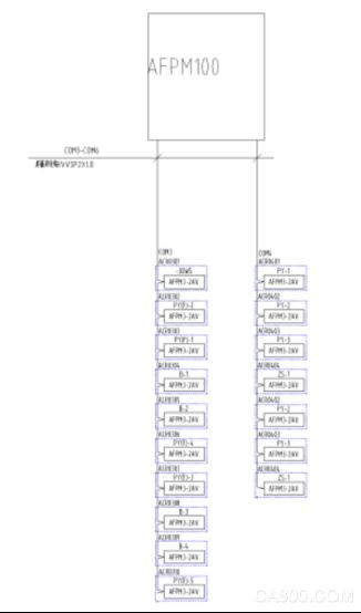

Application of AFPM100 Fire Equipment Power Monitoring System in Hangzhou Data Center Building Project
An Kerui Cui Tingyu
Jiangsu Ankerui Electric Appliance Manufacturing Co., Ltd.
Abstract: This article briefly describes the composition principle of the fire equipment power supply, and analyzes the design basis and relevant specifications of the fire equipment power monitoring system. Finally, an example of the installation of the Ankerui fire-fighting equipment power monitoring system in the Hangzhou Data Center Building was introduced to illustrate the implementation of the fire-fighting equipment power supply function and its significance.
Keywords: fire fighting equipment power supply; power supply monitoring module; monitoring system; AFPM100
0 Overview
AFPM fire-fighting equipment power monitoring system is an independent computer monitoring and control system integrated with Ankerui set monitoring, alarming and management. The system can be widely used in intelligent buildings, high-rise apartments, hotels, restaurants, commercial buildings, industrial and mining enterprises, national key firefighting Units and fields such as petrochemicals, culture, education, health, finance, and telecommunications.
The AFPM100 fire equipment power status monitor is the core of the AFPM fire equipment power monitoring system. The AFPM100 monitor is connected to multiple sensors through the RS485 bus to form a distributed fire protection equipment power monitoring system to monitor the working status of the main and standby power supplies in real time.
The monitor adopts a centralized and modular design and is equipped with sensors to monitor and control the voltage, current, and switch status of the fire-fighting equipment, such as operation-related information, alarm information, and fault information, as well as storage, analysis and statistics. Management; through the human-computer interaction interface, the data of fire-fighting equipment power supply is displayed in aggregate, with functions of management, viewing, alarm, and printing.
This project is a data center building in Hangzhou. A total of 17 AFPM3-2AV fire-fighting power supply monitoring modules are distributed on-site, and are installed in the fire-fighting distribution boxes of strong electric wells in the floors. The on-site fire power monitoring module adopts the bus mode to connect to the AFPM100 wall-mounted fire-fighting power supply monitoring system. The device has reasonable structure, high reliability, strong functions, convenient maintenance, and high cost performance. The system has a friendly interface and is easy to learn and use.
1 User needs
The project requires the fire equipment power monitoring system to monitor the faults and abnormal conditions of the power supply of the fire protection equipment of the Hangzhou Data Center Building Project, and promptly alert the relevant personnel to eliminate these hidden dangers and prevent the fire equipment from being available when there is a fire. Can not be put into use normally.
To facilitate on-duty monitoring and management, the central host has the following main functions:
1.1 According to the power distribution drawing, monitor the fire protection equipment of each circuit and master the operation of the power supply of the fire protection equipment.
1.2 The fire-fighting equipment power monitoring system can internally realize a unified monitoring platform and can obtain real-time data of all parameters within the system; intelligent management of the entire fire-fighting equipment power monitoring system can detect relevant information such as the voltage status of the fire-fighting equipment power supply. Determine whether the power supply of the fire-fighting equipment is open circuit, short-circuit, over-voltage, under-voltage, phase-missing, fault-equal fault information.
1.3 The host shall have the functions of real-time printing of event numbers, monitoring locations, nature of events, alarm parameters, and date and time data for monitoring alarms and fault alarm events. The alarm event data should be stored exclusively. There is an independent query interface that cannot be modified for analysis of fault liability.
1.4 In addition to the above requirements, the other functions and performance of the host should also comply with the provisions of the national standard GB 28184-2011 "Fire-fighting equipment power monitoring system" and GB 25506-2010 "General requirements for fire-fighting control room" standard.
2 Reference standards
2.1.GB25506-2010 "General technical requirements for fire control room", in section 5.7 Fire power monitor should meet the following requirements:
a) It should be able to display the working status and fault alarm information of the power supply and backup power supply for fire-fighting electrical equipment.
b) It should be able to transmit the working status and undervoltage alarm information of the power supply and standby power supply of the fire fighting equipment to the fire control room graphic display device.
2.2.GB 28184-2011 Fire Equipment Power Supply Monitoring System
2.3.GB 50116-2013 "Fire Automatic Alarm System Design Specification"
3 system components
The data monitoring and control system for the fire protection equipment in the Hangzhou Data Center Building consists of a fire-fighting equipment power monitoring host and a fire-fighting equipment power detector.
Two communication buses are connected to the project communication bus, and the detector module is connected to the wall-mounted host. AFPM100 fire-fighting equipment power monitoring system adopts a fire-fighting equipment power status monitor + voltage/current sensor two-layer structure networking mode. The entire monitoring system is full-featured, safe and reliable, with accurate detection and high cost performance. The system uses RS485 network communication internally and provides Modbus-RTU communication protocol externally to meet the connection of other standard systems. The above-mentioned sets of signals are stable and reliable. Fire equipment power monitoring system. The system network is divided into three layers:
3.1 Station Control Management
Station management The management personnel of the fire power monitoring system are the direct windows of human-computer interaction and the top part of the system. Mainly by the system software and necessary hardware devices, such as touch screen, UPS power supply and other components. The monitoring system software calculates, analyzes, and processes various types of data on the site, and responds to the on-site operations by means of graphics, digital display, sound, and indicator lights.
Monitoring host: used for data acquisition, processing and data forwarding. Provides data interfaces within or outside the system for system management, maintenance, and analysis.
UPS: Ensure the normal power supply of the computer monitoring system. When the power supply problem occurs in the entire system, ensure the normal operation of the station control and management equipment.
The monitoring host is set in the control room and is wall mounted.
3.2 Network Communication Layer
Communication medium: The system mainly adopts shielded twisted pair, uses RS485 interface and MODBUS communication protocol to realize real-time communication between field device and host computer.
3.3 Field device layer
The field device layer is a data acquisition terminal, which is mainly the AFPM100 series fire-fighting equipment power monitoring detector.
The system topology is as follows:
4 Fire Equipment Power Equipment
4.1. AFPM100 Fire Protection Equipment Power Supply Host
The main technical parameters:
Main power supply: AC220V 50Hz (Allow 85%-110% change)
Backup power supply: When the main power supply is low voltage or power failure, maintain the monitoring equipment working time ≥ 8h
Monitor provides DC24V power supply for connected modules (voltage/current signal sensors)
Work system: 24-hour work system
communication method:
Modbus-RTU communication protocol, RS485 half-duplex bus mode, transmission distance 500m (if you can extend the communication transmission distance through the repeater).
Operation classification
1 Daily shift: Real-time status monitoring and historical record query.
2 monitoring operation level: real-time status monitoring, history query, remote reset of the detector.
3 System management level: real-time status monitoring, history query, remote reset of the detector, remote modification of detector parameters, setting and modification of monitoring system parameters, and operator addition and deletion.
Use environmental conditions
1 Workplace: Fire control room, or in parallel with the fire control console
2 working environment temperature: -10 °C ~ +55 °C
3 Relative humidity of working environment: ≤95% non-condensing
4 Altitude: ≤2500m
5 Pollution Degree: Class III, Installation Category: Class III
4.2, AFPM100 series instruments
4.2.1, real-time monitoring of two-phase three-phase voltage;
4.2.2, with overvoltage, undervoltage, phase loss, phase error, overcurrent (only with current detection products) alarm;
4.2.3 Provide one or two channels (only monitor two-phase three-phase AC voltage products) switch quantity input function, which can monitor switch status; (see module selection)
4.2.4, provide a relay output, can be connected to the alarm control circuit;
4.2.5. With event storage function, the alarm can record the time, type, and parameter of the alarm. According to the alarm record, it can analyze the situation on the spot and provide a basis for eliminating the fault.
4.2.6, using fieldbus communication technology, the host computer management software can always monitor the operation of the scene, timely detection of alarm information. Through the RS485 interface, the standard MODBUS protocol can be connected to various standard systems;
4.2.7, high degree of integration, networking, high degree of intelligence, reasonable operating characteristics
5 system function
5.1, monitoring alarm function
Monitored equipment power circuit switch status
The working status of the monitored equipment power supply (voltage, current, and alarm status information)
Alarm response time: ≤100s
Alarm sound signal: can be manually eliminated, when the alarm signal input again, can start again
Alarm light signal: Red LED indicator is always on
5.2, control output function
Remote control of alarm relays for individual or all monitored devices
Monitor control output: normally open passive contact, capacity: AC250V 3A or DC30V 3A
5.3, fault alarm function
Disconnection and short circuit between the monitor and the module (voltage/current signal sensor)
Monitor mains undervoltage (≤80% mains voltage) or overvoltage (≥110% mains voltage)
Disconnection and short circuit between the monitor and its split power supply
When the monitor has the above fault, it can send a sound and light fault alarm signal that is obviously different from the monitoring alarm signal.
Fault alarm response time: ≤100s
Fault alarm sound signal: manual elimination, when the alarm signal input again, can start again
Fault alarm light signal: yellow LED indicator light
During faults, normal operation of non-failed circuits is not affected
5.4, ​​self-test function
Connection check: Disconnection and short circuit of communication lines and split power lines
Equipment self-test: manual or system self-test
Self-check time: ≤60s
5.5, alarm recording function
Record 10,000 related fault alarm information
Alarm Type: Fault Type, Occurrence Time, Fault Description
Alarm event query
Alarm record printing
5.6, print function
The monitoring system can print Chinese characters, and can print alarm events and time, fault events and time.
5.7 Silence
In the event of an alarm or malfunction such as an alarm, the monitoring device's speaker will give a corresponding alarm sound to prompt, press the "silence" key to terminate the alarm, the alarm light green light. During the period, staff can handle the relevant faults. Everything returned to normal and the alarm lights went out. If a new fault occurs, the silence indicator will turn off and the speaker will sound an alarm again.
6 Conclusion
The data monitoring system of the fire protection equipment of the Hangzhou Data Center Building Project consists of the fire equipment power monitoring device AFPM100 and the fire equipment power detector. AFPM fire-fighting equipment power monitoring system is an independent computer monitoring and control system integrated with Ankerui set monitoring, alarming and management. The system can be widely used in intelligent buildings, high-rise apartments, hotels, restaurants, commercial buildings, industrial and mining enterprises, national key firefighting Units and fields such as petrochemicals, culture, education, health, finance, and telecommunications. The AFPM100 fire-fighting equipment power status monitor is the core of the AFPM fire-fighting equipment power monitoring system. The monitoring equipment is connected to multiple sensors via an RS485 bus to form a distributed-type fire-fighting equipment power monitoring system to monitor the working status of the fire-fighting equipment power supply in real time. The controller adopts a centralized and modular design, and is equipped with a sensor to track, store, and analyze parameters such as the operation information, fault information, and location information of the monitored fire-fighting equipment power supply, facilitating user management and monitoring; The interactive interface integrates the data of the fire-fighting equipment power supply and has functions such as management, viewing, alarm, and printing. The device has reasonable structure, high reliability, strong functions, convenient maintenance, and high cost performance. The system interface is intuitive and easy to use.
references:
[1]. General Technical Requirements for Fire Control Room. Beijing. China Standard Press. 2011. 7
[2]. "Fire Equipment Power Monitoring System". Beijing. China Standard Press. 2011
About the author: Cui Tingyu, male, undergraduate, Jiangsu Ankerui Electric Manufacturing Co., Ltd., the main research direction for intelligent building power supply and distribution monitoring system. Email:el.cn QQ Mobile Phone Fax Website: http://