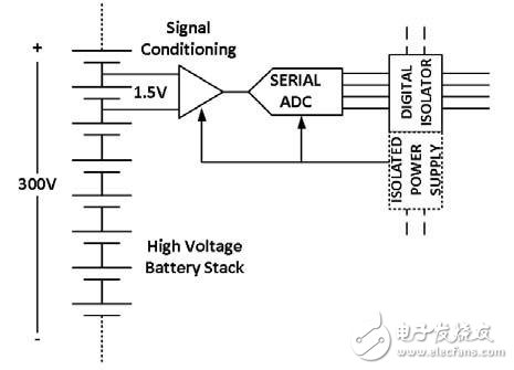
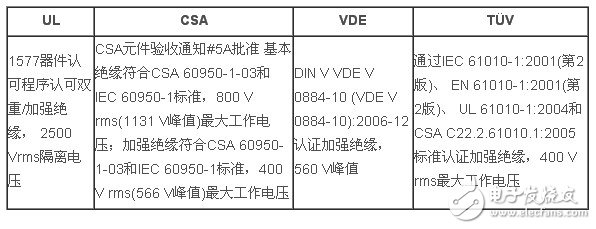
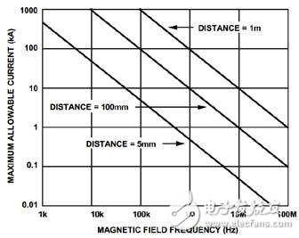
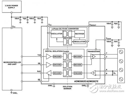
Executive summary Measurement devices used in industrial environments often require isolation to ensure user and system safety, as well as to ensure accurate measurements at high common-mode voltages. Digital isolators provide a reliable, easy-to-use alternative to older technologies such as optocouplers. With digital isolators, engineers can optimize isolation system designs to reduce power consumption and ensure system performance without the need for additional design margins to compensate for missing or incomplete device specifications. Introduction Designing isolated measurement instruments can be challenging and sometimes frustrating. The isolated front end protects the user from deadly voltages that may be present in the measurement system, while allowing engineers to make accurate measurements at high common-mode voltages. Figure 1 shows a typical example of such a measurement. In high-pressure fuel cells or battery packs, understanding the voltage of a single battery helps ensure safe operation of the system while maximizing battery life. When determining the voltage of a single battery, we must measure at a common mode voltage of up to several hundred volts. A similar situation occurs when the temperature of the current carrying conductor is measured with a thermocouple. In this case, the system must have the ability to measure millivolt-level signal resolution while suppressing high-level 60 Hz common-mode noise and protecting the operator from any dangerous voltage. Isolation amplifiers were originally used to solve this problem, but as measurement bandwidth and resolution grow, this solution is outdated. Now, the most accurate, economical, and efficient technique for performing such measurements is to isolate the entire measurement front end (including the analog-to-digital converter (ADC)) and implement an isolated serial link to the rest of the system, as shown in Figure 1. The link can be a local bus (such as SPI) or an industrial protocol (such as RS-485) to transmit measurement data over long distances to the controller unit. Figure 1. Measuring the voltage of a single battery in a high-voltage battery pack with an isolated front end Reliability design Until about 10 years ago, optocouplers were still one of the few viable solutions for isolating digital signals. However, if you ask an engineer who has to design with an optocoupler, you will understand how difficult it is to develop an efficient and reliable system with optocouplers, especially when you need to minimize costs. The optocoupler uses LEDs to generate light across the isolation barrier to turn the phototransistors on and off. When designing with an optocoupler, it must be ensured that the LED produces enough light to turn on the receiving phototransistor, while the output rise and fall times are also fast enough to support operation at the target frequency. One of the most important specifications for optocouplers is the current transfer ratio (CTR). CTR is the ratio of the collector current appearing on the phototransistor to the current through the LED. The optocoupler CTR not only has an extremely wide tolerance, but performance degrades over time and temperature. To ensure that the optocoupler can continue to operate after several years of use at high temperatures, engineers must assume the worst case CTR, which is inherently challenging because the optocoupler data sheet only lists the CTR specifications at room temperature. For example, the spec sheet for a typical optocoupler lists a guaranteed CTR of 50%–600% at 25°C. In addition, most data sheets contain typical graphs showing that the CTR at 80 °C is only about 50% of the CTR at 20 °C. In fact, no data sheet will list the minimum CRT at 85°C, so you must make assumptions about this value. In addition, some studies have simulated the decline in CTR over time, but this specification is also not listed in the data sheet, so you must decide how much additional design margin to increase to ensure that the final product is reliable over the life expectancy. Run. Designing a robust isolator circuit means that you have to make many engineering assumptions that require trade-offs between increased power consumption and reduced operating speed, leaving enough margin for the product to operate reliably throughout its lifetime. Digital isolators use non-optical methods to send data across the isolation barrier. For example, Analog Devices' isolators use micro-transformer technology to transmit pulses across the isolation barrier without the time and temperature drop effects associated with optocouplers. In this way, guaranteed minimum and maximum power, propagation delay, and pulse distortion specifications can be issued for the entire operating temperature range of the device. With full specifications, there is no need to perform extensive characterization of optocouplers under your operating conditions, and the data in the data sheet can be used directly to calculate worst-case system performance. You can use this data to calculate the top-level system timing specifications, just like any standard digital integrated circuit, by looking at the guaranteed isolation delay, skew, and power consumption of the digital isolator. Other non-optical techniques such as capacitive, radio frequency (RF) and giant magnetoresistance (GMR) coupling can also be used. Table 1. Regulatory Approvals for Analog Devices' ADuM140x Family of Digital Isolators. Since the magnetic digital isolator consumes most of its power from one state to another, the power consumption is proportional to the operating frequency. Therefore, the power consumption of the channel in an idle state or an extremely low switching speed is very small. Once the maximum serial clock rate of the application has been determined, the power supply can be designed to provide sufficient current to support this rate. When designing with optocouplers, it must be ensured that the circuit is always idle when the LED is off to minimize power consumption. Optocoupler technology has been on the market for more than 30 years; some engineers are cautious about moving to new isolator technology. Most manufacturers submit their products to regulatory approvals and clearly show which standards their isolators pass. Devices such as ADI's digital isolators use polyimide as an insulator, which is also used in many optocouplers. In some cases, they are tested to the same safety standards as optocouplers, while in other cases (such as VDE V 0884-10) specific standards have been developed specifically for digital isolators. For example, Table 1 shows the institutional certification for the ADuM140x series of isolators. Other issues relate to the ability of digital isolators to withstand overvoltage surges and their immunity to transients in the form of common-mode voltage and magnetic field interference. Fortunately, with polyimide insulation, Analog Devices' digital isolators can withstand surges of up to 6 kV for up to 10 seconds. Magnetic isolators have excellent Common Mode Transient Immunity (CMTI) over other technologies due to the extremely low parasitic capacitance on the isolation barrier. For example, typical high-speed optocouplers have CMTI specifications of 1 to 10 kV/μs, while magnetic digital isolators reject common-mode transients above 35 kV/μs. At first glance, the concern about magnetic field interference seems very reasonable, because the isolator with a micro-transformer uses a magnetic field to transmit pulses across the isolation barrier. One might think that a strong enough magnetic field can interfere with the pulse, causing an output error. However, since the radius of the transformer and its air core is very small, only a very large magnetic field or a very high frequency can cause a fault. The maximum allowable current and frequency shown in Figure 2 still guarantees that the output of the AD344x isolators is fault free. For example, only currents in excess of 500 A (1 MHz, 5 mm from the device) can trigger a fault output. In theory, the combination of amplitude and frequency required to produce an erroneous output far exceeds the range of most applications. Figure 2. ADuM344x guarantees maximum allowable current and frequency for error-free operation High speed operation Isolating a serial bus with an optocoupler can be a difficult task when an isolated measurement system uses a high sampling rate. The parasitic capacitance of the receiver photodiode limits the speed at which the optocoupler transmits digital signals. You can increase the charging speed of this parasitic capacitor by increasing the amount of light from the LED, but doing so will increase power consumption. In addition, few optocouplers provide more than two channels in the same direction in each package, and typically do not include timing specifications associated with channel-to-channel matching. While it is logical to assume a good match between optocouplers in the same package, the lack of printed specifications means you have to make engineering assumptions. As with non-printed specifications, most discreet engineers choose to leave ample design margins that are far below the performance indicated in the data sheet when using a single optocoupler. Another advantage of using a digital isolator is that the product can be used in a 4-channel device with a guaranteed speed of up to 150 Mbps. In addition, all digital isolator manufacturers provide guaranteed inter-channel matching specifications in the timing section of the data sheet. For example, Analog Devices' ADuM344x isolators guarantee a propagation-to-channel propagation delay mismatch of less than 2 ns over the entire operating temperature range. In practice, this means that digital isolators can be used at the speeds listed in the data sheet without the need to downgrade system performance for large or unknown inter-device or inter-channel skew. Figure 3. Full-duplex, isolated RS-485 interface with a single ADM2682E integrated Because digital isolator technology is compatible with standard CMOS processes, it is relatively easy to integrate additional features to simplify system design. For example, conventional thermocouple measurement devices may use multiple optocouplers to implement a low-speed SPI interface and use an isolation transformer with drivers and regulators to power the isolated front end. With digital isolators with integrated isolated power supplies, such as the ADuM5401, the entire isolation system becomes a single integrated circuit with four data channels and isolated power supplies. This approach improves reliability, saves board space, and reduces cost compared to using discrete isolators and isolated power supplies. Many instruments have an isolated RS-485 port for remote monitoring or control. A few years ago, implementing such an isolated port required not only the configuration of an isolator for the data line, but also a transceiver compatible with RS-485 differential signals and power. Figure 3 shows how a single IC like the ADM2682E integrates all functions into a single package. to sum up In the past, designing isolated measurement equipment was an expensive, difficult, and sometimes even frustrating task because of the many technical problems associated with optocouplers. In the past few years, advances in digital isolation technology have greatly simplified this task. Digital isolation technology features low cost, high performance, ease of use, and high integration, helping engineers complete development on time. In addition, regulatory agency certification and the ability to withstand high levels of interference make it ideal for long-life products commonly found in industrial measurement systems. The multi-speed air supply mode can bring you a comfortable and cool breeze in various scenarios. The 180° wide-angle surrounds the healthy and refreshing natural wind, and the soft wind blows on the face, returning to the natural and refreshing. The fuselage is equipped with a lanyard, so you can take the wind with you anytime anywhere. Neck Fan,Small Fan,Portable Mini Fan,Hanging Neck Fan Guangdong Aiyimi Electronic Technology Co., Ltd. , https://www.nbminifan.com