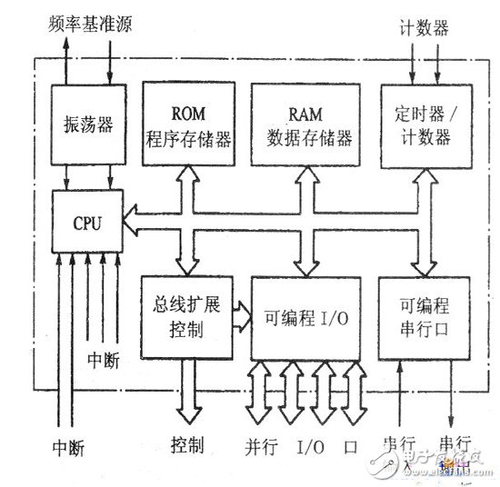
The basic block diagram of the PDP color TV microcontroller circuit is shown in the figure below. As can be seen from the figure, the microcontroller circuit is mainly composed of MCU and working condition circuit (power supply, reset, oscillation circuit), remote control receiving circuit, key input circuit, EEPROM data memory, Flash program memory, and switching control circuit (output level). Level), analog control circuit (output PWM pulse signal), I2C bus (parallel bus, serial bus, SPI bus) control circuit. The following is a brief introduction. 1. MCU and memory Most of the PDP color TVs use a microcontroller with 51 MCU as the core. It provides all the resources (ROM, I/O interface, etc.) that can be developed to the color TV manufacturer. The manufacturer can design the interface and program according to the needs of the application. Therefore, it has strong adaptability and is widely used. The figure below shows the block diagram of the MCU hardware. As can be seen from the figure, a basic MCU is mainly composed of the following parts: (1) CPU: The CPU plays a central role in the microcontroller. The receiving and executing instructions, various control functions, and auxiliary functions of all the operating action commands of the microcontroller are performed under the management of the CPU. At the same time, the CPU has to perform various computing tasks. (2) Memory: The internal memory of the MCU consists of two parts: 1 Random access memory RAM: used to store the intermediate data of the program running. During the working process of the microcontroller, the data may be rewritten, so the contents stored in the RAM can be changed at any time. It should be noted that after the color TV is powered off and the power is turned off, the data stored in the RAM will disappear. 2 read-only memory ROM: used to store programs and fixed data. The so-called program is a set of ordered instructions compiled according to the requirements of the problem to be solved and the instructions contained in the instruction system. The so-called data is the information, variables, parameters, tables, etc. in the MCU work process. When the color TV is turned off and the power is turned off, the programs and data stored in the ROM will not disappear. (3) Input/output (1/O) interface: The input/output interface circuit refers to the connection channel between the CPU and external circuits and devices and related control circuits. Due to the level of the external circuit and equipment, data format, operating speed, working mode, etc. are not uniform, in general, it is not compatible with the CPU (that is, it cannot be directly connected to the CPU). These external circuits and devices can only transmit and exchange information with each other through the input/output interface, so that the CPU can work in coordination with external circuits and devices. There are many types of input/output interfaces. Different external circuits and devices require corresponding input/output interface circuits. The method of programming can be used to determine the working mode, function and working state of the interface. Input/output interfaces can be divided into the following three categories: 1 Parallel input/output interface: Each lead can be flexibly selected as an input lead or an output lead. Some input/output leads are suitable for direct connection to other circuits, and some interfaces provide a large enough drive current. In the PDP color TV, the digital control pin and the analog control pin are parallel input/output ports. In addition, some MCUs allow the input/output interface to be used as a system parallel bus to extend the parallel bus memory and interface chip. 2 Serial Input/Output Interface: It is the simplest electrical interface. When serial communication with external circuits and devices, only a few signal lines are used. In PDP color TV, the serial input/output interface mainly has IIC serial bus interface (mounting EEPROM data memory and other IC with IIC bus interface) and SPI bus serial bus interface (mounting Flash program memory with SPI interface) ) two types. (4) Timer/Counter: In many applications of the MCU, it is often necessary to perform precise timing and generate a square wave signal, which is done by a timer/counter. Some timers also have an automatic reload function, which is more flexible and convenient to use, and it is easy to generate a programmable clock. When working in counter mode, pulses can be input from the specified input and counted. (5) System bus: Each basic circuit of the MCU is connected through an address bus (AB), a data bus (DB) and a control bus (CB), and then communicates with a circuit external to the MCU through a parallel input/output interface.
24HR Electronic timer socket with photocell.
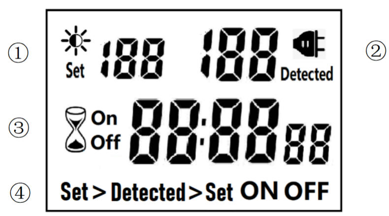
â‘ Light intensity setting
â‘¡ Light intensity detection
â‘¢ Countdown Timer ON & OFF
â‘£ 4 MODES:
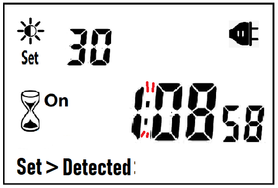
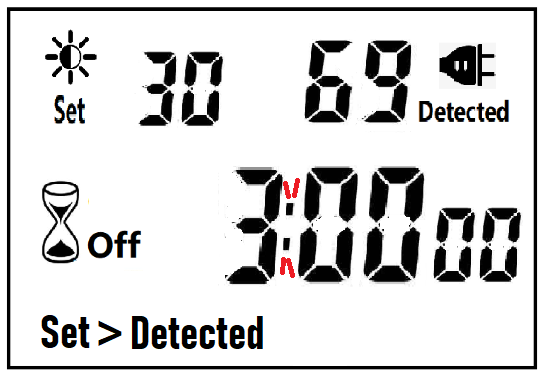
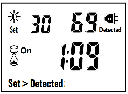
Set > Detected: When the light intensity detection value is less than the set value, switch ON or OFF.
Detected > Set: When the light intensity detection value is greater than the set value, switch ON or OFF
ON : Always ON
OFF : Always OFF
NOTED:
1. The light intensity displayed by this machine is not the standard light intensity value (Lux), only the relative light intensity value.
2. The light intensity value is affected by the placement position and direction. Please determine the position first and then set it according to the actual light intensity detected. If you change the position or change the orientation, you need to reset the light intensity setting value suitable for the new position.
3. This product has built-in rechargeable battery. If it is not connected to AC for a long time, you need to connect the power supply to charge until the LCD can display normally.
MANUAL OPERATION
1. Press [UP" or [DOWN" to set the LUX value.
2. Press the [SET" key to start setting, and the P1 settable items will be flashed.
3. Press [UP" or [DOWN" to adjust the value.
4. Press [SET" key again to exit setting or enter next setting for countdown timer.
5. Repeat the [SET" key to start setting, and the P2 & P3 settable items will be flashed.
6. Press the [FUN" key to switch the working state in the following:
Set > Detected -> Detected > Set -> ON -> OFF
Set > Detected: Automatically switches when the detected ambient light intensity is darker than the set value
Detected >Set: Automatically switch when the detected ambient light intensity is brighter than the set value
When the brightness meets the setting conditions, the countdown starts as below:
Note:when the countdown is ON, the detected value is not displayed.
When the brightness does not meet the setting conditions, the countdown stops and waits:
After the countdown ON is reduced to 0, the countdown OFF starts immediately and the power is OFF.
A. If the light intensity meets the set conditions, a new round of countdown will be started;
NOTE:
1. If the power is cut off while the countdown is running, the countdown will be terminated immediately and the relay output will be off. After the power is turned on again, a new round of brightness detection will start.
2. Modifying the brightness value in the countdown operation will not affect the current countdown operation. After the off time of the current countdown, the new brightness setting value will take effect.
3. In the countdown on operation, change the setting value of the countdown on, this countdown will still be timed according to the original setting value; the new setting value will take effect when the next countdown on starts.
Manual Control
Power Detection and Standby Mode
Photocell Timer, Photocell Timer Socket, Photocell Sensor, Photocell Sensor Socket, Sensor Plug, Sensor Switch Socket, Digital Photocell Timer, Digital Sensor Timer NINGBO COWELL ELECTRONICS & TECHNOLOGY CO., LTD , https://www.cowellsockets.com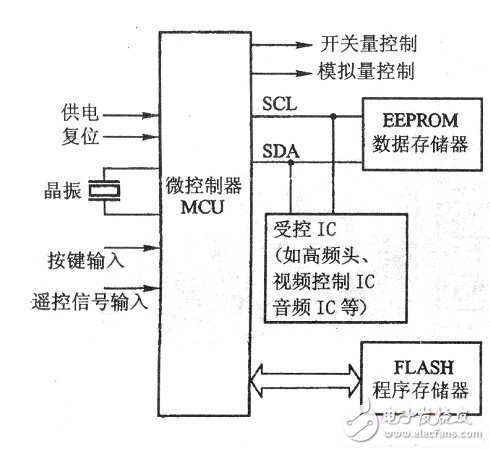


After the countdown OFF is reduced to 0:
B. If the light intensity does not meet the set conditions, keep the power off and wait for the light to meet the conditions before turning on automatically.
4. In the countdown off operation, change the setting value of countdown off, this countdown will still be timed according to the original setting value; the new setting value will take effect when the next countdown off is started.
NOTE: the brightness setting value, countdown ON or countdown OFF, any one of which is equal to 0, cannot be switched ON or OFF automatically.
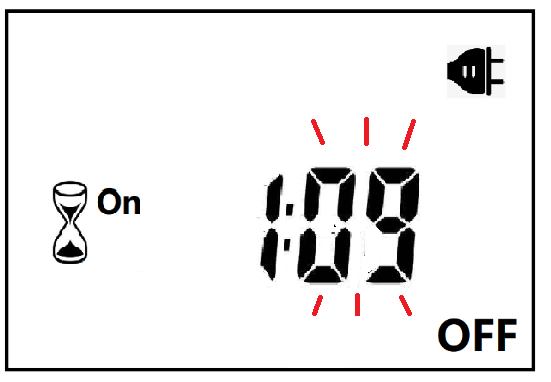
When ON or OFF is displayed, it means that the power supply remains ON or OFF, as shown in the figure below:

With AC power supply, the icon ![]() lights up and works normally.
lights up and works normally.
When there is no AC power supply, the icon ![]() goes out, the brightness is not detected at this time, and the system enters the standby mode.
goes out, the brightness is not detected at this time, and the system enters the standby mode.