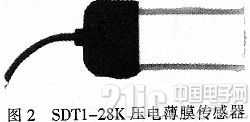
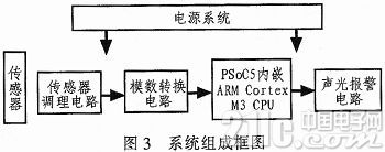
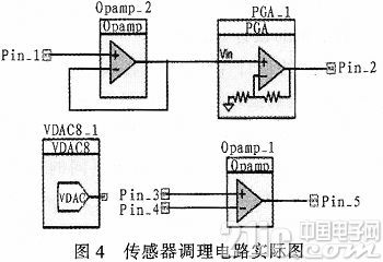
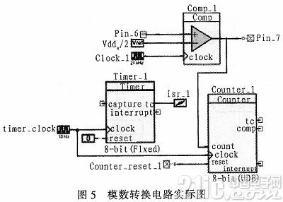
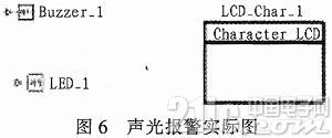
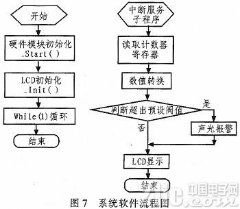
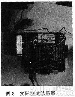
At present, wearable technology is emerging as a major technological change. Its essence is that it can be directly worn on the body, integrated into the clothes, and even implanted in the body related science and technology. The development of wearable technology will be more and more valued by the industry with the improvement of hardware technology, sensor technology, battery technology and communication technology, becoming the next explosive technology boom. This article refers to the address: http:// Piezoelectric film is a new type of polymer polymer sensing material with high piezoelectric constant, light weight, good flexibility, good processability and wide frequency response. Sensors fabricated using their piezoelectric characteristics have the advantages of simple structure, fast response rate, and simple processing at the back end, and have been widely used in health monitoring and bionics. A programmable system-on-chip is a programmable semiconductor device that has both a digital array of field-programmable gate arrays and an analog array of system-programmable analog devices with the ability to process both digital and analog signals. Programmable System-on-Chip Technology is a new embedded design that can be programmed during system operation to modify and reconstruct electronic systems, and is increasingly used in small system designs. The wearable sign monitoring system of the study combines piezoelectric film sensors and programmable system-on-chip technology to explore wearable technology in fire and clothing. 1 Technical analysis The system is based on CYPRESS's PSOC5 hardware platform resources, using the PSoC Creator2.0 software development platform, and using C language as the programming language to complete the implementation of the entire wearable sign monitoring system. The realization of the conditioning circuit based on the PSoC platform piezoelectric film sensor is completed. The realization is based on the implementation of the PSoC platform analog-to-digital conversion circuit. The realization of the sound and light alarm circuit based on the PSoC platform is completed, and the system software is designed and implemented. 1.1 PSoC5 System Architecture The following is a description of the CY8C55 family of low-power, on-chip programmable systems using one of the optional 32-bit PSoC5 platforms. The main components of the CY8C55 series are shown in Figure 1: ARM Cortex M3 CPU subsystem, non-volatile subsystem, programming debug subsystem, digital and analog subsystems, clock and power modules. Due to the remarkable features of the PSoC system, designers can be freed from the cumbersome low-level programming. The software platform can provide a rich library of devices and functions, improve design efficiency, shorten design cycles, and accelerate prototype molding. When the design requirements change, it can be quickly modified. The new product update does not need to change too much, the integration is high, and the multiple functions are all in one, which is convenient for research and development, procurement, and production, thus reducing the cost. 1.2 Piezoelectric film sensor The piezoelectric film sensor is selected from MESUREMENT's SDT1-28K model, as shown in Figure 2. The SDT1 piezoelectric film sensor consists of a rectangular piezoelectric film and a molded plastic housing with a coaxial cable. The surface of the piezoelectric material is printed with silver ink and folded over itself, allowing the sensor to self-shield. This application in high standard EMI environments is quite important. The sensor operates in a relative mode, and the length of the piezoelectric film changes to produce a corresponding charge, so that a voltage appears at the electrode end of the film. The sensor acts like a "positive" capacitor, so the load impedance matching problem must be considered when loading the input signal to the measuring device. Due to the extremely thin film thickness, the resulting parasitic capacitance and standard 1 MΩ load are sufficient to constitute a low frequency response. 2 Technology implementation The researchable wearable sign monitoring system consists of three parts: sensor conditioning circuit, analog-to-digital conversion circuit, and sound and light alarm circuit. The entire system components are shown in Figure 3 below. 2.1 Design and implementation of sensor conditioning circuit The piezoelectric film sensor is a passive sensor, and the differential output of the passive sensor is a low differential voltage (millivolts). The output impedance is relatively high, so the signal requires a level of amplification. Moreover, the common mode signal is difficult to suppress and requires a differential amplification. Figure 4 shows the configuration of the simulation section, implemented by the graphical configuration tool PSoCCreator. The first stage of the input module consists of an op amp with a gain of 1 voltage follower as an impedance match between the sensor and the load. After this stage, it is a programmable gain amplifier with a gain G fixed to 4. After this stage of pre-amplification, a secondary amplification with offset compensation is required. Offset compensation is due to the initial bias of the sensor, so a 9-bit DAC must be compensated. The second-order amplification is a second-order active low-pass filter circuit composed of an operational amplifier, and the gain G is between 1 and 48. All offset compensation and gain are automatically selected by the firmware based on actual needs. After the signal is filtered, the voltage amplitude is between PSoC's analog ground, AGND, and Vcc/2. The secondary amplification is made up of Opamp_1 with a reference voltage Vdda. The last amplified signal is fed into a special analog-to-digital conversion circuit constructed by a timer and counter. 2.2 Design and implementation of analog-to-digital conversion circuit After the analog pulse response signal passes through the sensor conditioning circuit, the ideal signal waveform after conditioning will be sent to a special analog-to-digital conversion circuit composed of a voltage comparator, a counter, and a timer. Figure 5 shows the configuration of the actual design of the analog-to-digital conversion circuit, implemented by the graphical configuration tool PSoC Creator. The conditioned signal amplitude satisfies the level value required by the PSoC's built-in voltage comparator. The voltage comparator determines the logic level and outputs it at the rising edge of each clock according to the parameters of the firmware configuration and the reference voltage Vref of the comparator. Since the amplitude of the signal after conditioning is approximately 1.2 V, the reference level of the system to the voltage comparator is 1.2 V, and the frequency of the clock is set to 24 K (only need to be greater than the frequency of pulse vibration), the voltage comparator The output is counted by the counter. At the same time, the timer is used to generate a time interval of 6 s, during which the counter counts. After the timer is interrupted, the Cortex-M3 microcontroller embedded in the PSoC performs interrupt processing, reconfigures the timer and counter, and converts the value of the counter to display the result through the LCD. 2.3 Design and implementation of sound and light alarm circuit The design of the sound and light alarm circuit is that when the system detects abnormal data, it can respond accordingly to prompt the user to take corresponding measures. When the software determines that the value after the counter is abnormal, the code of the emergency alarm part will be executed. Different schemes are selected between the threshold and the excess value to perform different operations on the buzzer and the LED lamp. On the hardware circuit, the buzzer and the LED light are configured on the PSoC hardware platform. In use, only the firmware is configured with the pin assignment scheme, and the corresponding pin can be connected by the DuPont line. Figure 6 shows the complete design of this module circuit. 2.4 System software design and implementation The main part of the software part of the system is to configure the various hardware modules required by PSoC. The initialization of the module, the configuration of the parameters, and the implementation of the RESET function of the module are implemented in the software. In addition, the software also has an important function, which is to complete the display function of the pulse vibration number and the sound and light alarm function in the emergency state in the timer interrupt service program. The system software flow chart is shown in Figure 7. PSoC Creator 2.0 provides software design in both assembly and C language. The software execution part is shown in the flow chart. The initial human body pulse analog quantity becomes a relatively practical digital quantity after passing through the piezoelectric film sensor, sensor conditioning circuit and analog-to-digital conversion circuit. The digital quantity will first be displayed on the LCD display, giving an intuitive feeling. At the same time, the program will compare this generated digital quantity with a preset threshold (the range of a normal person's pulse beat number). If the digital quantity is within this normal range, the green light is always on and the buzzer does not sound; if the digital value jumps above the threshold of the normal range, the red light flashes and the buzzer sounds. After starting the program, the program first initializes each hardware module. As can be seen from the above, the required hardware modules are: operational amplifier (Opamp), programmable amplifier (PGA), voltage comparator (Comp), timer (Timer), Counter, character display (LCD), clock module, interrupt module, etc. When the program is initialized, it will go directly to the infinite loop guided by the for function. The main code execution of the function will be in the interrupt service subroutine of the timer CY_ISR (Intermpt Handler). Interrupt service subroutine in timer The main operations are as follows: configuration of the counter state and reading of its register; data conversion of the counter count; call of the LCD to display the result; threshold determination to determine whether to execute the emergency sound and light alarm module, the timer Status configuration, etc. In summary, the development of the PSoC programmable system-on-chip is quite simple, and the hardware resources and software resources on it are quite rich, and the two are well integrated. On the hardware, the user can focus on the overall function of the system design, avoiding the difficulty of debugging the discrete component building system. In software, PSoC's API for driver packaging of various hardware modules is also quite clever, and program development has become simple and concise. 3 system test Since this system is a practical platform for medical and fire protection, it is necessary to conduct practical application tests to check whether it is suitable for most people. In the actual test process, especially when operating the piezoelectric film sensor, attention must be paid to the operation instructions of the SDT1 piezoelectric film sensor proposed by MEASUREMENT. The test connection method is shown in Figure 8. 4 Conclusion The system basically realizes the function of vital sign monitoring and has an alarm function, which can be applied in the field of smart clothing proposed in this paper to improve the rescue effect of firefighters. At the same time, this system has improved the traditional fire emergency measures and joined the modern electronic information system to improve the overall fire efficiency. In addition, it can be seen from the basic functions of the system that the electronic system can also be applied in the fields of medical electronic equipment, clinical medical monitoring, etc., and has wide application and expansion.
Power distribution cabinet (box) includes power distribution cabinet (box), lighting distribution cabinet (box) and metering cabinet (box), which are the last level equipment of power distribution system. Power distribution cabinet is the general name of motor control center. The power distribution cabinet is used where the load is relatively dispersed and the circuit is less; Motor control center is used for occasions with concentrated load and many loops. They distribute the electric energy of a circuit of the upper level distribution equipment to the nearest load. This class of equipment shall provide protection, monitoring and control for the load.
classification:
(1) The primary power distribution equipment is collectively referred to as the power distribution center. They are centrally installed in the substation of the enterprise and distribute electric energy to the subordinate distribution equipment in different locations. This level of equipment is close to the step-down transformer, so the requirements for electrical parameters are high, and the output circuit capacity is also large.
low voltage incoming cabinet,Reactive compensation cabinet,feeder cabinet,Control cabinet,high voltage switchgear Henan New Electric Power Co.,Ltd. , https://www.newelectricpower.com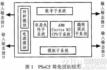
(2) Secondary power distribution equipment is the general name of power distribution cabinet and motor control center. The power distribution cabinet is used where the load is relatively dispersed and there are few loops; Motor control center is used for occasions with concentrated load and many loops. They distribute the electric energy of a circuit of the upper level distribution equipment to the nearest load. This class of equipment shall provide protection, monitoring and control for the load.
(3) The final power distribution equipment is generally called lighting power distribution box. They are far away from the power supply center and are scattered small capacity power distribution equipment
